Hardware options installation 56
10.
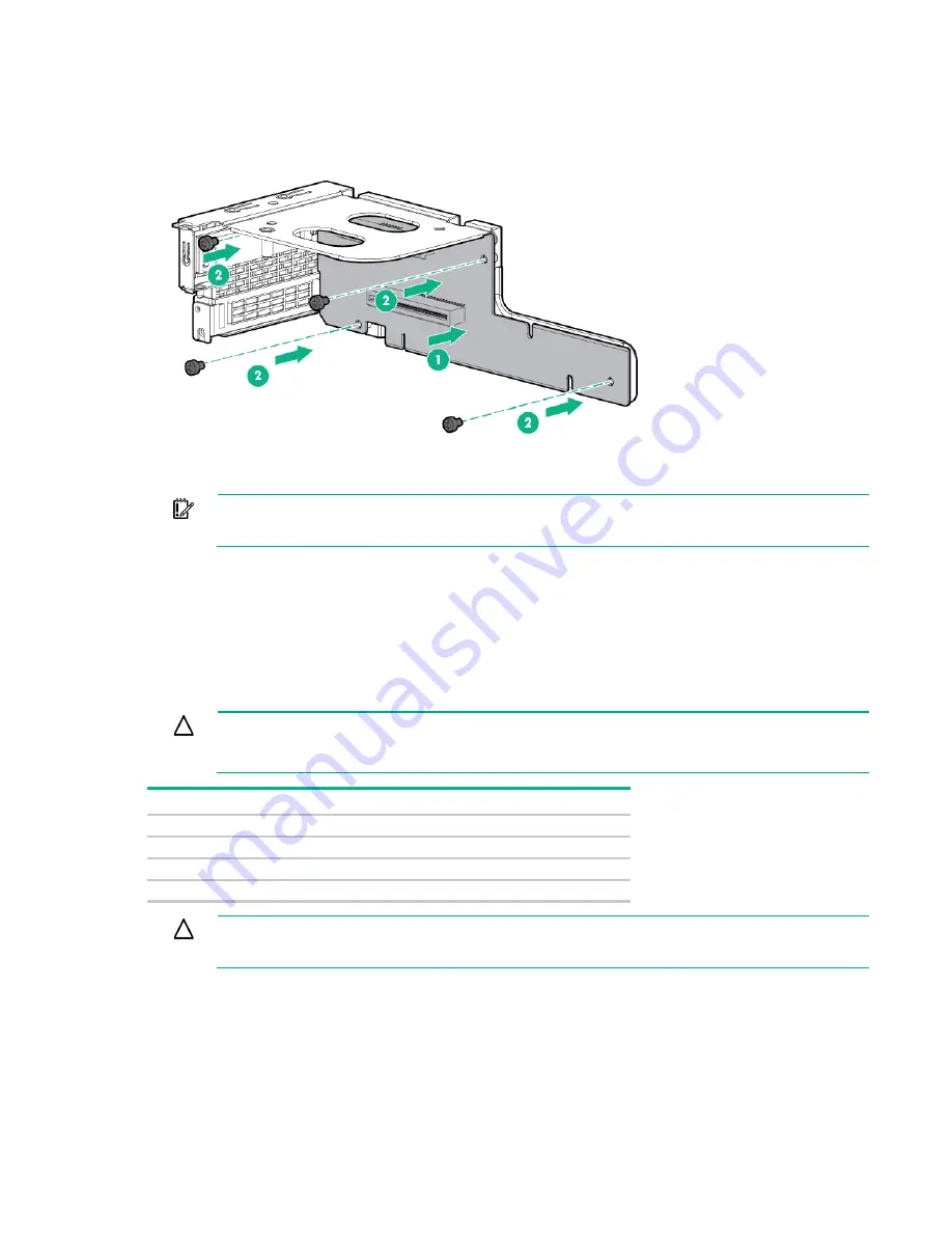
Install the riser card into the PCI cage.
11.
If necessary, install the expansion boards ("
Installing an expansion board or FlexibleLOM
" on page
IMPORTANT:
The server does not power up if the PCI riser board assembly is not seated
properly.
12.
Connect all internal cabling to the expansion boards.
13.
Install all components removed from the server.
14.
Install the server into the chassis ("
Installing the server into the chassis
" on page
15.
Power up the server (on page
Redundant hot-plug power supply option
CAUTION:
All power supplies installed in the server must have the same output power
capacity. Verify that all power supplies have the same part number and label color. The system
becomes unstable and may shut down when it detects mismatched power supplies.
Label color
Output
Orange
750 W
Green
1,200 W
White
1,200 W -48Vdc
Yellow
1,500 W
CAUTION:
To prevent improper cooling and thermal damage, do not operate the server
unless all bays are populated with either a component or a blank.
To install the component:
1.
Unfasten the cable management solution to access the power supply bays.
Summary of Contents for ProLiant SL270s Gen8
Page 16: ...Operations 16 5 Remove the shipping plates 6 Remove the hard drive cage...
Page 17: ...Operations 17 7 Loosen screws securing the GPU shelf 8 Remove the GPU shelf...
Page 36: ...Hardware options installation 36 5 Remove the shipping plates 6 Remove the hard drive cage...
Page 47: ...Hardware options installation 47 o Left node o Right node...
Page 49: ...Hardware options installation 49 5 Remove the shipping plates 6 Remove the hard drive cage...
Page 50: ...Hardware options installation 50 7 Loosen screws securing the GPU shelf 8 Remove the GPU shelf...
Page 53: ...Hardware options installation 53 4 Remove all shipping brackets 5 Remove the shipping plates...
Page 55: ...Hardware options installation 55 8 Remove the GPU shelf 9 Remove the PCI cage...
Page 59: ...Hardware options installation 59 5 Remove the shipping plates 6 Remove the hard drive cage...
Page 60: ...Hardware options installation 60 7 Loosen screws securing the GPU shelf 8 Remove the GPU shelf...
Page 72: ...Cabling 72 Right node Capacitor pack to FBWC on controller card cabling o Left node...
Page 73: ...Cabling 73 o Right node...
Page 97: ...Support and other resources 97...
Page 98: ...Support and other resources 98...
Page 106: ...Index 106 V ventilation 19 W warnings 21 website Hewlett Packard Enterprise 91...


