


access pint into the slots. Release the button to secure the access point to the mounting bracket. See
.
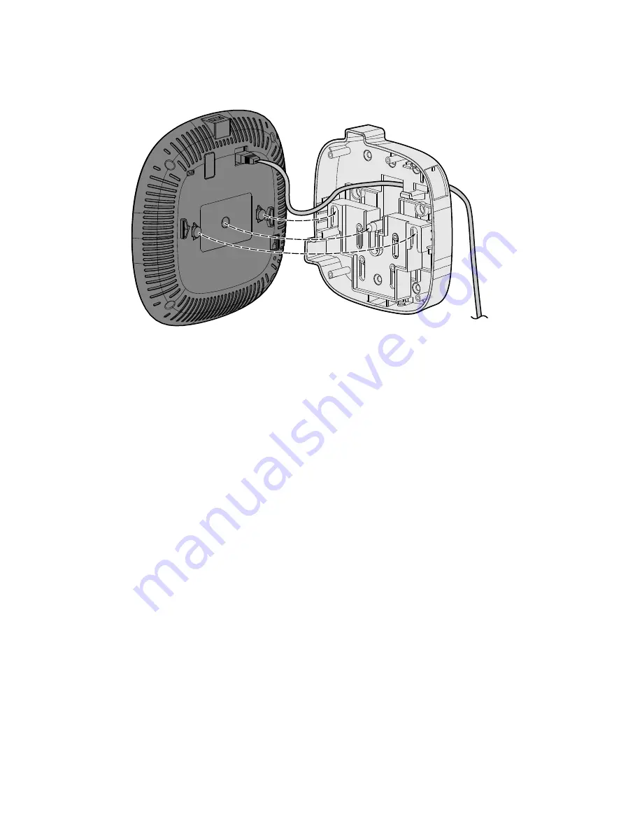
Figure 6
Securing the Access Point to the Mounting Bracket
4. To lock the access point to the mounting bracket, insert the T6 Torx security screw into the hole beside
the button, located at the bottom of the mount. then tighten until the screw is snug.
Installing the Mount Bracket to a DIN or European Wall Box
1. Align the holes on the mounting bracket with the corresponding holes on the wall box. To install this kit
to a single gang wall box, refer to
. Then, using the M4x10 machine screws, fasten the mount
housing to the wall box using the holes indicated.