background image

Docking connector (display)

Description

Spare part number

Docking connector

902356-001

Before removing the docking connector, follow these steps:

1.

Turn off the tablet. If you are unsure whether the tablet is off or in Hibernation, turn the tablet on, and 
then shut it down through the operating system.

2.

Disconnect the power from the tablet by unplugging the power cord from the tablet.

3.

Disconnect all external devices from the tablet.

4.

Remove the back cover (see 

Back cover on page 22

).

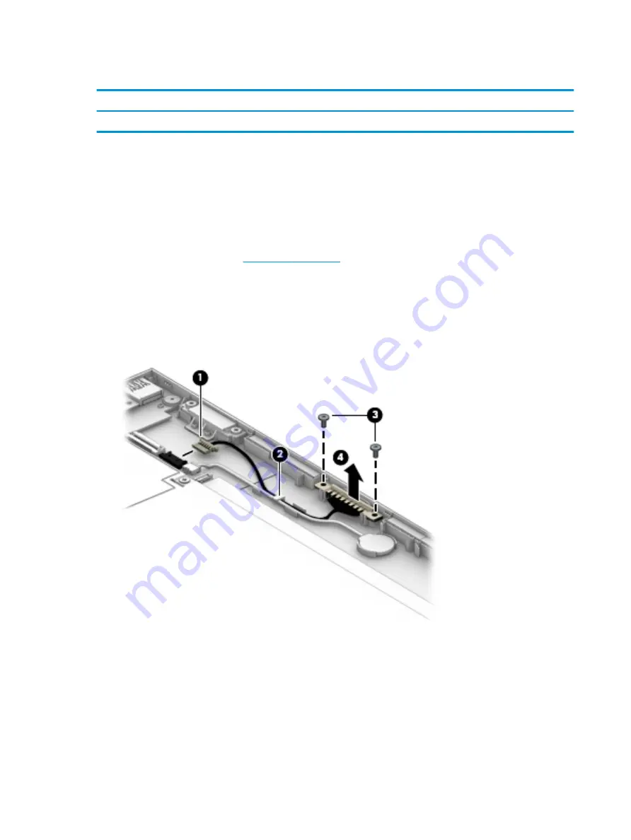
Remove the docking connector:

1.

Disconnect the docking connector from the system board (1), and remove the cable from the clip built 
into the display enclosure (2).

2.

Remove the two Phillips PM2.0×4.0 screws (3) that secure the docking connector to the display panel 
assembly, and then remove the docking connector (4).

Reverse this procedure to install the display docking connector.

24

Chapter 5   Removal and replacement procedures

Summary of Contents for x2 Detachable 10-p0XX

Page 1: ...HP x2 Detachable PC Model numbers 10 p0XX HP x2 210 G2 Detachable PC Maintenance and Service Guide IMPORTANT This document is intended for HP authorized service providers only ...

Page 2: ...Part Number 903182 001 Product notice This guide describes features that are common to most models Some features may not be available on your computer Not all features are available in all editions of Windows This computer may require upgraded and or separately purchased hardware drivers and or software to take full advantage of Windows functionality See http www microsoft com for details Software...

Page 3: ... another hard surface such as an adjoining optional printer or a soft surface such as pillows or rugs or clothing to block airflow Also do not allow the AC adapter to contact the skin or a soft surface such as pillows or rugs or clothing during operation The device and the AC adapter comply with the user accessible surface temperature limits defined by the International Standard for Safety of Info...

Page 4: ...iv Safety warning notice ...

Page 5: ... 15 Rubber Kit 16 Miscellaneous parts 17 4 Removal and replacement preliminary requirements 18 Tools required 18 Service considerations 18 Plastic parts 18 Cables and connectors 18 Grounding guidelines 19 Electrostatic discharge damage 19 Packaging and transporting guidelines 20 Workstation guidelines 20 5 Removal and replacement procedures 22 Tablet component replacement procedures 22 Back cover ...

Page 6: ... 53 Determining the BIOS version 53 Downloading a BIOS update 54 7 Using HP PC Hardware Diagnostics UEFI 56 Downloading HP PC Hardware Diagnostics UEFI to a USB device 56 8 Specifications 58 9 Backing up restoring and recovering 59 Creating recovery media and backups 59 Creating HP Recovery media select products only 59 Using Windows tools 60 Restore and recovery 61 Recovering using HP Recovery Ma...

Page 7: ...10 Power cord set requirements 65 Requirements for all countries 65 Requirements for specific countries and regions 65 11 Recycling 67 Index 68 vii ...

Page 8: ...viii ...

Page 9: ...ush glass multitouch enabled Memory On board system memory DDR3L 1600 single channel support 2048 MB 256Mx16 x4pcs LPDDR3 1600 single channel support LPDDR3 1866 1 2V downgraded to LPDDR3 1600 4096 MB 256Mx16x4x2pcs Supports up to 4 GB maximum system memory Mass storage Tablet eMMC TLC configurations 128 GB HP x2 210 G2 models only 64 GB 32 GB Dock Single hard drive configurations HP x2 models onl...

Page 10: ... Micro Secure Digital SD Media Reader Support SD SDHC SDXC Push push insertion removal Ports Tablet Headphone microphone combo jack One USB 3 0 port One USB 2 0 type C port supporting charging and data Micro HDMI v1 4a port supporting up to 1920x1080 60Hz Pogo pin 6 pin docking connector Keyboard Keyboard Detachable hard keyboard cover 93 island style thin cover non backlit keyboard 1 5 mm travel ...

Page 11: ...t Preinstalled HP x2 210 G2 models Windows 10 Home 64 Entry Tablet 2 in 1 Notebook Compact Windows 10 Home 64 Entry Tablet 2 in 1 Notebook Single Language Compact Windows 10 Home 64 Chinese Market CPPP Compact Windows 10 Pro 64 Tablet 2 in 1 Notebook Compact Windows 10 Pro 64 Tablet 2 in 1 Notebook Chinese Market Compact Windows 10 Pro 64 StF MSNA Compact Windows 10 Pro 64 StF MSNA EM Compact Wind...

Page 12: ...isplay cover Allows you to video chat record video and record still images 3 Camera light On The camera is in use 4 Speakers 2 Produce sound 5 Rear camera Allows you to video chat record video and record still images The antennas are not visible from the outside of the computer and antenna location varies For optimal transmission keep the areas immediately around the antennas free from obstruction...

Page 13: ...iate Sleep When the tablet is in the Sleep state press the button briefly to exit Sleep When the tablet is in Hibernation press the button briefly to exit Hibernation CAUTION Pressing and holding down the power button will result in the loss of unsaved information If the tablet has stopped responding and Windows shutdown procedures are ineffective press and hold the power button down for at least ...

Page 14: ...tal or audio component or a high speed High Definition Multimedia Interface HDMI device 3 AC adapter and battery light White The AC adapter is connected and the battery is fully charged Blinking white The AC adapter is disconnected and the battery has reached a low battery level Amber The AC adapter is connected and the battery is charging Off The battery is not charging 4 USB Type C power connect...

Page 15: ...ng on headphones earbuds or a headset For additional safety information refer to the Regulatory Safety and Environmental Notices To access this guide Select the Start button select All apps select HP Help and Support and then select HP Documentation NOTE When a device is connected to the jack the computer speakers are disabled 2 Volume button Controls speaker volume on the tablet Bottom edge Compo...

Page 16: ... 3 are located on the tablet bottom edge This information may be needed when travelling internationally or when contacting support Component 1 Quick Response QR code 2 Serial number 3 Product number 4 Warranty period 5 Model number select models only 8 Chapter 2 External component identification ...

Page 17: ...ves and changes product parts For complete and current information on supported parts for your computer go to http partsurfer hp com select your country or region and then follow the on screen instructions Tablet major components Tablet major components 9 ...

Page 18: ...01 13 LCD shielding includes thermal pad 902363 001 14 System board equipped with an Intel Atom x5 z8350 processor and a graphics subsystem with UMA memory includes replacement thermal material For use in HP x2 210 G2 models Equipped with a 128 GB eMMC hard drive SoC 4 GB of system memory and the Windows 10 operating system 903879 601 Equipped with a 128 GB eMMC hard drive SoC 4 GB of system memor...

Page 19: ...C hard drive SoC 4 GB of system memory and the Windows 10 operating system 902253 601 Equipped with a 32 GB eMMC hard drive SoC 4 GB of system memory and Windows 7 or a non Windows operating system 902253 001 15 Hinge assembly NOTE The hinge assembly is not spared as a whole unit For more information about hinge subcomponents see Hinge components on page 14 not spared 16 Back cover Silver HP x2 an...

Page 20: ... HP x2 210 models without a hard drive Silver models 902345 001 For use in HP x2 models without a hard drive White models 902346 001 Red models 902347 001 For use in models HP x2 models with a hard drive Silver models 902348 001 White models 902349 001 12 Chapter 3 Illustrated parts catalog ...

Page 21: ...ite models 907508 001 Red models 907509 001 TouchPad cable for use in HP x2 and HP x2 210 G2 models without a hard drive not illustrated 902357 001 TouchPad cable for use in HP x2 models with a hard drive not illustrated 902358 001 8 Top cover keyboard For a list of keyboard country codes see Top cover keyboard on page 52 HP x2 and HP x2 210 G2 models without a hard drive Silver 902365 xx1 HP x2 m...

Page 22: ... Red HP x2 models 902379 001 2 Hinge Mylar 3 Hinge bezel 4 Pogo docking connector For use in HP x2 and HP x2 210 G2 models without a hard drive 902359 001 For use on HP x2 models with a hard drive 902360 001 5 Magnets not spared 6 Hinge cover Silver HP x2 and HP x2 210 G2 models 902374 001 White HP x2 models 902375 001 Red HP x2 models 902376 001 14 Chapter 3 Illustrated parts catalog ...

Page 23: ...ut a hard drive 902357 001 For use in HP x2 models with a hard drive 902358 001 2 Audio board cable 902351 001 3 Display LCD cable 902354 001 4 Volume board cable 902353 001 5 Front webcam cable 902355 001 6 Power button board cable 902352 001 7 Rear webcam not spared 8 Docking cable 902359 001 Cables 15 ...

Page 24: ...nd HP x2 210 G2 models 902384 001 White HP x2 models 902385 001 Red HP x2 models 902386 001 Rubber Kit for use in models with a hard drive models Silver HP x2 models 902387 001 White HP x2 models 902388 001 Red HP x2 models 902389 001 1 Screw covers 2 Bottom rubber strip 16 Chapter 3 Illustrated parts catalog ...

Page 25: ...13350 009 For use in India 404827 003 For use in Israel 398063 003 For use in Italy 213352 008 For use in Japan 349756 002 For use in North America 213349 009 For use in South Africa 361240 002 For use in South Korea 267836 008 For use in Switzerland 213354 008 For use in Taiwan 393313 003 For use in Thailand 285096 006 For use in the United Kingdom and Singapore 213351 008 RJ 45 USB adapter 53961...

Page 26: ...astic parts Use care when handling the plastic parts Apply pressure only at the points designated in the maintenance instructions Cables and connectors CAUTION When servicing the tablet be sure that cables are placed in their proper locations during the reassembly process Improper cable placement can damage the tablet Cables must be handled with extreme care to avoid damage Apply only the tension ...

Page 27: ...e these precautions Keep components in their electrostatic safe containers until you are ready to install them Before touching an electronic component discharge static electricity by using the guidelines described in this section Avoid touching pins leads and circuitry Handle electronic components as little as possible If you remove a component place it in an electrostatic safe container The follo...

Page 28: ... proper materials are selected to avoid static charging When grounding is not possible use an ionizer to dissipate electric charges Workstation guidelines Follow these grounding workstation guidelines Cover the workstation with approved static shielding material Use a wrist strap connected to a properly grounded work surface and use properly grounded tools and equipment Use conductive field servic...

Page 29: ...m resistance between the operator and ground To be effective the conductive must be worn in contact with the skin The following grounding equipment is recommended to prevent electrostatic damage Antistatic tape Antistatic smocks aprons and sleeve protectors Conductive bins and other assembly or soldering aids Nonconductive foam Conductive tabletop workstations with ground cords of one megohm resis...

Page 30: ...and replacement Back cover Description Spare part number Back cover Silver HP x2 and HP x2 210 G2 models 902342 001 White HP x2 models 902343 001 Red HP x2 models 902344 001 Display panel Silver HP x2 and HP x2 210 G2 models 902380 001 White HP x2 models 902381 001 Red HP x2 models 902382 001 Display cable 902354 001 Before disassembling the tablet follow these steps 1 Turn off the tablet If you a...

Page 31: ... to disengage the top and bottom of the display 1 3 Remove the back cover 2 4 Disconnect the battery cable from the system board 1 5 Disconnect the display cable from the system board 2 and then remove the display from the enclosure 3 Reverse this procedure to install the back cover Tablet component replacement procedures 23 ...

Page 32: ... the power cord from the tablet 3 Disconnect all external devices from the tablet 4 Remove the back cover see Back cover on page 22 Remove the docking connector 1 Disconnect the docking connector from the system board 1 and remove the cable from the clip built into the display enclosure 2 2 Remove the two Phillips PM2 0 4 0 screws 3 that secure the docking connector to the display panel assembly a...

Page 33: ...er from the tablet by unplugging the power cord from the tablet 3 Disconnect all external devices from the tablet 4 Remove the back cover see Back cover on page 22 Remove the RTC battery 1 Disconnect the battery cable from the system board 1 and remove the cable from the clip built into the display enclosure 2 2 Lift the battery to disengage the adhesive that secures it to the display enclosure 3 ...

Page 34: ...rom the tablet 3 Disconnect all external devices from the tablet 4 Remove the back cover see Back cover on page 22 Remove the front webcam module 1 Disconnect the webcam cable from the system board 1 2 Lift the microphone rubber piece up and off the right side of the module 2 3 Remove the cable from its routing path 3 4 Remove the webcam module 4 from the display panel assembly The webcam module c...

Page 35: ...ing the power cord from the tablet 3 Disconnect all external devices from the tablet 4 Remove the back cover see Back cover on page 22 5 Remove the battery see Battery on page 29 Remove the antenna 1 Peel the antenna off the shield 1 2 Disconnect the antenna cable from the system board 2 3 Remove the antenna cable from its routing path in the display enclosure 3 4 Remove the antenna from the displ...

Page 36: ...g system 2 Disconnect the power from the tablet by unplugging the power cord from the tablet 3 Disconnect all external devices from the tablet 4 Remove the back cover see Back cover on page 22 Remove the LCD shield 1 Peel the antenna off the shield 1 2 Remove the 10 Phillips PM2 0 2 5 screws 2 that secure the shield to the display 3 Lift the shield from the display panel assembly 3 Reverse this pr...

Page 37: ...e Back cover on page 22 5 Remove the LCD shield see LCD shield on page 28 WARNING To reduce potential safety issues use only the battery provided with the tablet a replacement battery provided by HP or a compatible battery purchased from HP CAUTION Removing a battery that is the sole power source for the tablet can cause loss of information To prevent loss of information save your work or shut dow...

Page 38: ...he tablet 3 Disconnect all external devices from the tablet 4 Remove the back cover see Back cover on page 22 5 Remove the LCD shield see LCD shield on page 28 Remove the speakers 1 To remove the right speaker disconnect the speaker cable from the system board 1 2 Remove the speaker cable from its routing path in the display assembly 2 3 Remove the right speaker 3 4 To remove the left speaker remo...

Page 39: ...6 Remove the speaker 3 Reverse this procedure to install the speakers Tablet component replacement procedures 31 ...

Page 40: ... external devices from the tablet 4 Remove the back cover see Back cover on page 22 5 Remove the LCD shield see LCD shield on page 28 6 Remove the battery see Battery on page 29 Remove the audio board 1 Release the ZIF connector 1 to which the audio board cable is attached and then disconnect the audio jack board cable from the audio board 2 Remove the Phillips PM2 0 2 0 screw 2 that secures the a...

Page 41: ...om the tablet 3 Disconnect all external devices from the tablet 4 Remove the back cover see Back cover on page 22 5 Remove the LCD shield see LCD shield on page 28 6 Remove the battery see Battery on page 29 Remove the power button board 1 Remove the Phillips PM2 0 2 0 screw 1 that secures that secures the power button board to the display panel assembly 2 Lift the top of the board upward 2 and th...

Page 42: ...5 Remove the power button board 6 Reverse this procedure to install the power button board 34 Chapter 5 Removal and replacement procedures ...

Page 43: ...let by unplugging the power cord from the tablet 3 Disconnect all external devices from the tablet 4 Remove the back cover see Back cover on page 22 5 Remove the LCD shield see LCD shield on page 28 6 Remove the battery see Battery on page 29 Remove the volume board 1 Disconnect the cable from the volume board 1 2 Remove the two Phillips PM2 0 2 0 screws 2 that secure the volume board to the displ...

Page 44: ... power cord from the tablet 3 Disconnect all external devices from the tablet 4 Remove the back cover see Back cover on page 22 5 Remove the LCD shield see LCD shield on page 28 6 Remove the left speaker see Speakers on page 30 Remove the rear webcam module 1 Lift the bracket from atop the webcam module 1 2 Disconnect the webcam cable from the system board 2 3 Remove the webcam module 3 from the d...

Page 45: ...rear webcam lens from inside of the display enclosure pull the lens up to remove it The lens is secured with adhesive Reverse this procedure to install the rear webcam module Tablet component replacement procedures 37 ...

Page 46: ...or a non Windows operating system 902252 001 32 GB eMMC hard drive SoC 4 GB of system memory and the Windows 10 operating system 902253 601 32 GB eMMC hard drive SoC 4 GB of system memory and Windows 7 or a non Windows operating system 902253 001 Before removing the system board follow these steps 1 Turn off the tablet If you are unsure whether the tablet is off or in Hibernation turn the tablet o...

Page 47: ...Phillips PM2 0 2 0 screw 1 that secures the system board to the display panel assembly 3 Lift the right side of the system board up 2 and then pull the board toward the right away from the connectors on the side of the display and then out of the display enclosure 3 Reverse this procedure to install the system board Tablet component replacement procedures 39 ...

Page 48: ...d HP x2 210 G2 models without a hard drive Silver models 902345 001 Bottom cover for use in HP x2 models without a hard drive White models 902346 001 Red models 902347 001 Remove the bottom cover 1 Place the dock upside down on a flat surface 2 Remove the two screw covers 1 and two silver Phillips PM2 0 4 0 screws 2 3 Remove the rubber strip from the bottom cover 3 4 Remove the four black Phillips...

Page 49: ...6 Remove the bottom cover 6 Reverse this procedure to install the bottom cover Dock component replacement procedures 41 ...

Page 50: ...ver see Bottom cover on page 40 Remove the hard drive 1 Remove the four Phillips PM2 0 3 0 screws 1 that secure the hinges to the dock 2 Pull the hard drive away from the connector 2 and then remove the hard drive from the dock 3 3 To remove the hard drive brackets remove the four Phillips PM3 0 3 0 screws 1 that secure the brackets to the hard drive 42 Chapter 5 Removal and replacement procedures...

Page 51: ...ls with a hard drive Description Spare part number Docking board hard drive models 902372 001 Before disassembling the dock follow this step Remove the bottom cover see Bottom cover on page 40 Remove the docking board 1 Remove the two Phillips PM2 0 2 0 screws 1 that secure the board to the dock 2 Disconnect the touchpad cable from the docking board 2 Dock component replacement procedures 43 ...

Page 52: ...s the connector on the bottom 3 4 Disconnect the keyboard cable from the docking board 4 5 Remove the docking board from the dock 5 Reverse this procedure to install the docking board 44 Chapter 5 Removal and replacement procedures ...

Page 53: ...om cover see Bottom cover on page 40 Remove the docking board 1 Disconnect the keyboard cable from the docking board 1 2 Disconnect the touchpad cable from the docking board 2 3 Remove the two Phillips PM2 0 2 0 screws 3 that secure the board to the doc 4 Remove the docking board from the dock 4 Reverse this procedure to install the docking board Dock component replacement procedures 45 ...

Page 54: ...use in HP x2 models with a hard drive 902358 001 Before removing the TouchPad board follow this step Remove the bottom cover see Bottom cover on page 40 Remove the TouchPad board 1 Disconnect the cable from the TouchPad 1 2 Remove the three black Phillips PM2 0 2 0 screws 2 3 Lift the bracket off the board 3 4 Remove the three broadhead silver Phillips PM2 0 2 0 screws 4 5 Remove TouchPad board fr...

Page 55: ...e hinge assembly follow this step Remove the bottom cover see Bottom cover on page 40 Remove the hinge assembly 1 Disconnect the cable from the system board 1 2 Rotate the hinge assembly up to a 45 degree angle 2 3 Remove the four Phillips PM2 0 3 0 screws 3 that secure the hinge assembly to the dock 4 Remove the hinge assembly from the dock 4 Reverse this procedure to install the hinge assembly D...

Page 56: ...Mylar The Mylar is secured with adhesive and is reusable The Mylar is available in the hinge bezel kit using the following spare part numbers Silver HP x2 and HP x2 210 G2 models 902377 001 White HP x2 models 902378 001 Red HP x2 models 902379 001 2 To remove the hinge bezel remove the two silver outer Phillips PM2 0 6 0 screws 1 3 Remove the black middle Phillips PM2 0 5 0 screw 2 4 Use a tool to...

Page 57: ...bers Silver HP x2 and HP x2 210 G2 models 902377 001 White HP x2 models 902378 001 Red HP x2 models 902379 001 6 Remove the Phillips PM2 0 4 0 screw from each bracket 1 7 Lift the brackets away from each hinge 2 Left and right hinge brackets are available using spare part number 902364 001 8 Remove the Phillips PM2 0 5 0 screw 1 from the docking connector Dock component replacement procedures 49 ...

Page 58: ...number 902359 001 for HP x2 and HP x2 210 G2 models without a hard drive and 902360 001 for HP x2 models with a hard drive The hinge cover is available using the following spare part numbers Silver HP x2 and HP x2 210 G2 models 902374 001 White HP x2 models 902375 001 Red HP x2 models 902376 001 50 Chapter 5 Removal and replacement procedures ...

Page 59: ...r installation location for the magnets Hinge assembly magnet installation locations Display assembly magnet installation locations Reverse this procedure to install the wireless antenna Dock component replacement procedures 51 ...

Page 60: ...HP x2 models with a hard drive Silver models 902680 xx1 White models 902681 xx1 Red models 902682 xx1 For use in country or region Spare part number For use in country or region Spare part number For use in country or region Spare part number Belgium A41 Israel BB1 Slovenia BA1 Bulgaria 261 Italy 061 South Korea AD1 Canada DB1 Japan 291 Spain 071 Czech Republic and Slovakia FL1 Latin America 161 S...

Page 61: ...ets without keyboards 1 Turn on or restart the tablet and then quickly hold down the volume up button or Turn on or restart the tablet and then quickly hold down the volume down button or Turn on or restart the tablet and then quickly hold down the Windows button 2 Tap f10 Updating Setup Utility BIOS Updated versions of Setup Utility BIOS may be available on the HP website Most BIOS updates on the...

Page 62: ...re installing any software updates especially system BIOS updates 1 Type support in the taskbar search box and then select the HP Support Assistant app or Click the question mark icon in the taskbar 2 Click Updates and then click Check for updates and messages 3 Follow the on screen instructions 4 At the download area follow these steps a Identify the most recent BIOS update and compare it to the ...

Page 63: ...ilename exe The BIOS installation begins 5 Complete the installation by following the on screen instructions NOTE After a message on the screen reports a successful installation you can delete the downloaded file from your hard drive Updating Setup Utility BIOS 55 ...

Page 64: ... The BIOS searches three places for the diagnostic tools in the following order a Connected USB drive NOTE To download the HP PC Hardware Diagnostics UEFI tool to a USB drive see Downloading HP PC Hardware Diagnostics UEFI to a USB device on page 56 b Hard drive c BIOS 3 When the diagnostic tool opens select the type of diagnostic test you want to run and then follow the on screen instructions NOT...

Page 65: ...the product name or number or Select Identify now to let HP automatically detect your product 4 Select your computer and then select your operating system 5 In the Diagnostic section follow the on screen instructions to select and download the UEFI version you want Downloading HP PC Hardware Diagnostics UEFI to a USB device 57 ...

Page 66: ... for IT power systems in Norway with phase to phase voltage not exceeding 240 V rms NOTE The tablet operating voltage and current can be found on the system regulatory label Temperature Operating 5 C to 35 C 41 F to 95 F Nonoperating 20 C to 60 C 4 F to 140 F Relative humidity non condensing Operating 10 to 90 Nonoperating 5 to 95 Maximum altitude unpressurized Operating 15 m to 3 048 m 50 ft to 1...

Page 67: ... the HP Recovery partition on the computer The backup can be used to reinstall the original operating system in cases where the hard drive is corrupted or has been replaced For information on creating recovery media see Creating HP Recovery media select products only on page 59 For information on the recovery options that are available using the recovery media see Using Windows tools on page 60 Us...

Page 68: ...rately to create recovery discs If you use an external optical drive it must be connected directly to a USB port on the computer the drive cannot be connected to a USB port on an external device such as a USB hub If you cannot create DVD media yourself you can obtain recovery discs for your computer from HP See the Worldwide Telephone Numbers booklet included with the computer You can also find co...

Page 69: ...o remove the recovery partition to reclaim hard drive space HP Recovery Manager offers the Remove Recovery Partition option For more information see Removing the HP Recovery partition select products only on page 64 Recovering using HP Recovery Manager HP Recovery Manager software allows you to recover the computer to its original factory state by using the HP Recovery media that you either create...

Page 70: ...or a recovery USB flash drive This type of recovery can be used only if the hard drive is still working To start HP Recovery Manager from the HP Recovery partition IMPORTANT For a tablet with a detachable keyboard connect the keyboard to the keyboard dock before beginning these steps select products only 1 Type recovery in the taskbar search box select Recovery Manager and then select HP Recovery ...

Page 71: ...e the boot order IMPORTANT For a tablet with a detachable keyboard connect the keyboard to the keyboard dock before beginning these steps 1 Insert the HP Recovery media 2 Access the system Startup menu For computers or tablets with keyboards attached Turn on or restart the computer or tablet quickly press esc and then press f9 for boot options For tablets without keyboards Turn on or restart the t...

Page 72: ...overy partition So before you remove the Recovery partition create HP Recovery media see Creating HP Recovery media select products only on page 59 NOTE The Remove Recovery Partition option is only available on products that support this function Follow these steps to remove the HP Recovery partition 1 Type recovery in the taskbar search box and then select HP Recovery Manager 2 Select Remove Reco...

Page 73: ...must be approved by an acceptable accredited agency responsible for evaluation in the country or region where the power cord set will be used The power cord sets must have a minimum current capacity of 10 amps and a nominal voltage rating of 125 or 250 V AC as required by the power system of each country or region The appliance coupler must meet the mechanical configuration of an EN 60 320 IEC 320...

Page 74: ...and wall plug must bear a T mark and registration number in accordance with the Japanese Dentori Law The flexible cord must be Type VCT or VCTF 3 conductor 1 00 mm conductor size The wall plug must be a two pole grounding type with a Japanese Industrial Standard C8303 7 A 125 V configuration 4 The flexible cord must be Type RVV 3 conductor 0 75 mm conductor size Power cord set fittings appliance c...

Page 75: ...he battery in general household waste Follow the local laws and regulations in your area for battery disposal HP encourages customers to recycle used electronic hardware HP original print cartridges and rechargeable batteries For more information about recycling programs see the HP Web site at http www hp com recycle 67 ...

Page 76: ...ents 12 docking board spare part number 13 docking board hard drive models removal 43 spare part number 43 docking board no hard drive models removal 45 spare part number 45 docking connector removal 24 spare part number 24 docking port identifying 7 E electrostatic discharge 19 equipment guidelines 21 external expansion product description 2 external optical drive spare part number 17 F front web...

Page 77: ...ass storage 1 memory module 1 microphone 1 operating system 3 ports 2 power requirements 2 processors 1 product name 1 sensor 2 serviceability 3 webcam 1 wireless networking 2 product name 1 R rear camera identifying 4 rear webcam module removal 36 spare part number 36 recover options 61 recovery discs 60 62 HP Recovery Manager 61 media 62 starting 62 supported discs 60 system 61 USB flash drive 6...

Page 78: ...lume board cable spare part number 10 W webcam product description 1 webcam front removal 26 spare part number 26 webcam rear module removal 36 spare part number 36 Windows system restore point 59 60 Windows tools using 60 wireless networking product description 2 workstation guidelines 20 70 Index ...

Reviews: