NOTE:
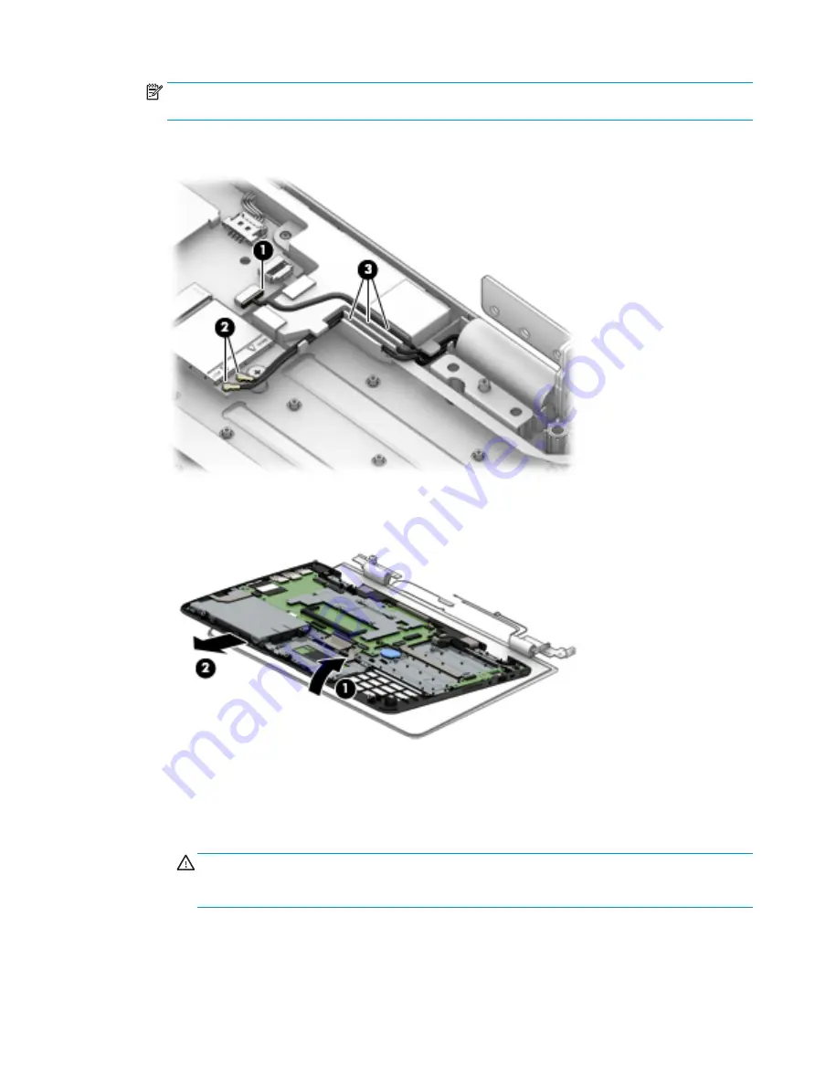
The #1/white wireless antenna cable connects to the WLAN module #1/Main terminal. The #2/
black wireless antenna cable connects to the WLAN module #2/Aux terminal.
11.
Release the G-sensor module cable and the wireless antenna cables from the retention clips (3) and
routing channel built into the speaker.
12.
Swing the keyboard/top cover (1) up and away from the display assembly.
13.
Slide the keyboard/top cover (2) up and forward at an angle and separate it from the display assembly.
14.
If it is necessary to replace the display panel assembly or any of the display assembly subcomponents:
a.
Use a case utility tool (1) or similar plastic, flat-edged tool to separate the top edge (2) of
the display panel assembly from the display back cover.
b.
Separate the left (3) and rights sides of the display panel assembly from the display back cover.
CAUTION:
As you prepare to remove the display panel assembly, carefully remove the display
panel cable and the G-sensor board cable from the opening (4) in the display right hinge. Failure to
follow this caution can result in damage to the display panel cable and the G-sensor board cable.
Component replacement procedures
59


