


Chassis configuration setting
When migrating a SAN Director with two domains (two logical
switches) to a 4/256 SAN Director, the result will be a SAN Director
with only one domain. Depending on your configuration, this
may change the topology of the fabric and should be taken into
consideration when planning your installation.
The 4/256 SAN Director supports chassis configuration options 1 or
5 only. Use the
chassisConfig
command to change the chassis
configuration. The valid options are:
•
Option 1 — One (up to) 128-port logical switch. This chassis mode
supports CP4 control processor blades managing FC4–16.
•
Option 5 — One (up to) 384-port logical switch. This chassis mode
supports CP4 control processor blades managing the FC4–16,
FC4–32, and FC4–48.
Blade components and port numbering
The following sections illustrate 4Gb SAN Director Port Blade
components.
FC4–16 Port Blade components
identifies FC4–16 blade components and the port numbering
scheme. Ports are numbered from 0 through 15 from bottom to top.
15
14
13
12
11
10
56
-00005
90
-0
1 R
ev A
!
7
6
5
4
3
2
1
0
15
14
13
12
11
10
9
8
56
-00005
90
-01 R
ev A
!
FC4
16
1
2
3
4
5
6
7
8
25027a
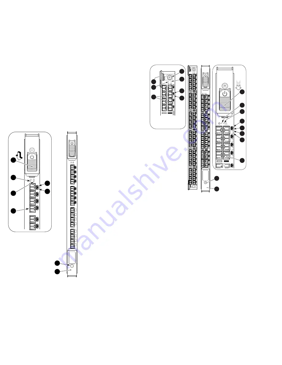
Figure 1 FC4–16 components
Callouts
1.
On/Off switch (On position)
5.
Port speed LED
2.
Power LED
6.
Port status LED
3.
Status LED
7.
Thumb screw
4.
Fibre Channel port
8.
Ejector
FC4–32 and FC4–48 Port Blade components
identifies FC4–32 and FC4–48 blade components and port
numbering schemes.
For the FC4–32, ports are numbered from 0 through 15 from bottom to
top on the left set of ports, and 16 through 31 from bottom to top on
the right set of ports.
For the FC4–48, ports are numbered from 0 through 23 from bottom to
top on the left set of ports and 24 through 47 from bottom to top on
the right set of ports.
24
0
25
1
26
2
27
3
28
4
29
5
30
6
31
7
32
8
33
9
34
10
35
11
36
12
37
13
38
14
39
15
40
16
41
17
42
18
43
19
44
20
45
21
46
22
47
23
!
44
20
45
21
46
22
47
23
!
31
15
30
14
29
13
28
12
27
11
26
10
25
9
24
8
23
7
22
6
21
5
20
4
19
3
18
2
17
1
16
0
!
FC4
32
!
31
15
30
29
27
14
13
28
12
1
25225a
2
3
4
5
6
7
8
9
10
11
12
13
14
15
16
17
Figure 2 FC4–48 (left) and FC4–32 (right) components
Callouts
1.
On/Off switch (on position)
10.
On/Off Switch (Off position)
2.
FC4–48 power LED
11.
FC4–32 power LED
3.
FC4–48 Fibre Channel ports
12.
FC4–32 status LED
4.
Thumb screw
13.
FC4–32 port speed LED
5.
FC4–48 status LED
14.
FC4–32 port status LED
6.
FC4–48 port status LED
15.
Port speed LED for FC4–32
(for FC4–32 this LED indicates
the port speed for the left port)
7.
Port status LED for FC4-32
and FC4-48 (for FC4–32 and
FC4–48, this LED indicates the
port status for the left port)
16.
Port status LED for FC4–32
and FC4–48 (for FC4–32 and
FC4–48, this LED indicates the
port status for the left port)
8.
Thumb screw
17.
Fibre Channel port
9.
Ejector
Page 2


