background image

4.

Verify that the fan status LED is lit steady green to indicate normal operation.

5.

Optionally, display the fan status using the

fanshow

command from the CLI.

8/80 SAN Switch and Encryption SAN Switch FRU units

Replace the following FRUs as required:

Fan assembly

Power supply

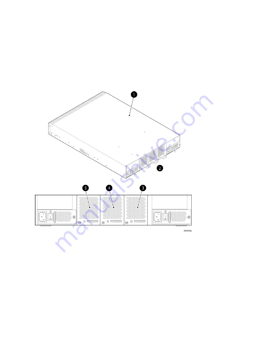
The 8/80 SAN Switch and Encryption SAN Switch integrate three fan assemblies (see

Figure 36

).

Fabric OS identifies the fans from left to right as Fan assembly #3, Fan assembly #2, and Fan assembly
#1.

4. Fan assembly #2

1. 8/80 SAN Switch

5. Fan assembly #3

2. Nonport side

3. Fan assembly #1

Figure 36 8/80 and Encryption SAN Switch fan assemblies on the nonport side

.

Managing the 8-Gb SAN Switches

78

Summary of Contents for StorageWorks 1606 - Extension SAN Switch

Page 1: ...formation on installing configuring and maintaining the 8 Gb SAN family of HP StorageWorks Fibre Channel switches This document is intended for system administrators and technicians with knowledge of SANs and HP StorageWorks Fibre Channel switches Part Number 5697 0291 Sixth edition July 2010 ...

Page 2: ...dor s standard commercial license The information contained herein is subject to change without notice The only warranties for HP products and services are set forth in the express warranty statements accompanying such products and services Nothing herein should be construed as constituting an additional warranty HP shall not be liable for technical or editorial errors or omissions contained herei...

Page 3: ...E Converged Network Switch 21 Nonport side of the FCoE Converged Network Switch 21 1606 Extension SAN Switch features 21 Feature comparison of base and upgraded products 23 Available licenses 23 Port side of the 1606 Extension SAN Switch 24 Nonport side of the 1606 Extension SAN Switch 25 Installing and activating Port Upgrade licenses 25 SAN Switch ISL Trunking groups 26 Supported SFP transceiver...

Page 4: ...Extension SAN Switch 56 FCIP and Fibre Channel routing services configuration 56 Verifying switch operation 57 8 Gb SAN Switch LEDs 58 8 8 and 8 24 SAN Switch LEDs 58 8 40 SAN Switch LEDs 59 8 80 SAN Switch LEDs 60 Port side LED activity for the 8 80 SAN Switch 61 Nonport side LED activity for the 8 80 SAN Switch 63 Port side LED activity for the Encryption SAN Switch 64 Port side LED activity for...

Page 5: ... 96 Typographic conventions 97 Customer self repair 98 A Regulatory compliance and safety 99 Regulatory compliance 99 Federal Communications Commission notice for Class A equipment 99 Modifications 99 Cables 99 Regulatory compliance identification numbers 99 Laser device 99 Laser safety warning 100 Certification and classification information 100 Laser product label 100 International notices and s...

Page 6: ...ice 106 Italian notice 106 Latvian notice 107 Lithuanian notice 107 Polish notice 107 Portuguese notice 107 Slovakian notice 108 Slovenian notice 108 Spanish notice 108 Swedish notice 108 B Electrostatic discharge 111 How to prevent electrostatic discharge 111 Grounding methods 111 Glossary 113 Index 119 6 ...

Page 7: ...8 15 Installing the outer rails HP 10000 Series rack 39 16 Assembling the outer rails HP 10000 Series rack 39 17 Assembling the outer rails HP System e rack 40 18 Securing the inner rails to an MP Router 41 19 Securing the inner rails to the 4 64 SAN Switch 41 20 Attaching the plenum to a 4 8 or 4 16 SAN Switch 42 21 Securing the switch HP 9000 Series or HP 10000 Series racks 43 22 Securing the de...

Page 8: ...er row of port slot 75 34 Nonport side LEDs 76 35 8 80 and Encryption SAN Switch fan assemblies on the nonport side 78 36 Inserting the fan assembly in the 8 80 SAN Switch 80 37 Installing a power supply in the 8 80 or Encryption SAN Switch 81 38 Class 1 laser product label 100 39 8 ...

Page 9: ...escription and required actions 77 15 Management tools 83 16 8 Gb SAN Switch physical dimensions 85 17 8 8 8 24 and 8 40 SAN Switch memory 86 18 8 80 SAN Switch Encryption SAN Switch and FCoE Converged Network Switch memory 86 19 1606 Extension SAN Switch memory 86 20 Facility requirements 86 21 EMC 87 22 Power supply specifications 88 23 Laser data transmission ranges for the 8 8 and 8 24 SAN Swi...

Page 10: ...Document conventions 97 31 10 ...

Page 11: ...P StorageWorks 8 8 Full Fabric SAN Switch Ships with 8 ports activated and includes a Full Fabric license Advanced Web Tools Advanced Zoning and EGM as standard software compon ents HP StorageWorks 8 24 SAN Switch Ships with 16 ports activated and includes a Full Fabric li cense It includes Advanced Web Tools Advanced Zoning and EGM as standard software components HP StorageWorks 8 40 SAN Switch S...

Page 12: ...sion SAN Switch Ships with 6 Fibre Channel SFP ports and two active GbE ports It includes a Full Fabric license HP StorageWorks 1606 Extension Power Pack SAN Switch Ships with 16 Fibre Channel SFP ports 6 active GbE ports base software Full Fabric Advanced Fabric OS Advanced Web Tools and Advanced Zoning and Power Pack software Adaptive Networking Fabric Watch ISL Trunking Extended Fabric and Adva...

Page 13: ...gure 1 shows the port side of the 8 8 and 8 24 SAN Switch 5 Fibre Channel status LEDs 1 System status top and power bottom LEDs 6 Fibre Channel ports 24 2 System RS 232 console port RJ 45 7 AC power inlet 3 Ethernet port with two Ethernet status LEDs 4 USB port Figure 1 Port side view 8 8 and 8 24 SAN Switch Nonport side of the 8 8 and 8 24 SAN Switch The nonport side is used solely for airflow Th...

Page 14: ...and integrated peripherals which provide high performance Ships FICON and FICON Cascading ready FICON CUP is available but requires an optional license Provides two hot swappable redundant integrated power supply and fan FRUs Universal ports that self configure as E_Ports F_Ports M_Ports or FL_Ports EX_Ports are activated on a per port basis with the optional HP B series 48 80 Port SAN Switch Inte...

Page 15: ...1 1 Fan for power supply fan FRU2 6 Power supply fan status LED for power supply fan FRU 1 2 Power supply fan status LED for power supply fan FRU2 7 Power supply connector for power supply fan FRU 1 3 Power supply connector for power supply fan FRU2 8 Fan for power supply fan FRU1 4 Fan for power supply fan FRU2 Figure 3 Nonport side view 8 40 SAN Switch Activating additional 8 40 SAN Switch ports...

Page 16: ...n to provide hardware redundant cooling Provides universal ports that self configure as E_Ports F_Ports M_Ports or FL_Ports EX_Ports are activated on a per port basis with the optional HP B series 48 80 Port SAN Switch Integrated Routing LTU This license provides native FCR on a per port basis rather than limiting routing ports to those on a dedicated routing blade or switch Just like traditional ...

Page 17: ... 63 6 USB port 15 FC ports 64 71 7 FC ports 0 7 16 FC ports 72 79 8 FC ports 8 15 Figure 4 Port side view 8 80 SAN Switch Nonport side of the 8 80 SAN Switch and the Encryption SAN Switch Figure 5 shows the nonport side of the 8 80 SAN Switch and the Encryption SAN Switch which contains the power supplies including the AC power receptacle and AC power switch and fans 8 Gb SAN Switch Hardware Refer...

Page 18: ...talling and activating Port Upgrade licenses page 25 Encryption SAN Switch features The Encryption SAN Switch has the following features 32 front end 1 2 4 or 8 Gb s autosensing F_Port FL_Port E_Port EX_Port or M_Ports to connect host servers SAN disks SAN tapes edge switches or core switches Encryption and decryption engines to provide in line crypto services with up to 96 Gb s throughput for dis...

Page 19: ...NOTE The full range of 1 2 4 and 8 Gb s can be achieved only by a combination of 4 Gb s SFPs 1 2 and 4 Gb s and 8 Gb s SFP 2 4 and 8 Gb s Fabric OS support delivering distributed intelligence throughout the network and enabling a wide range of applications including Web Tools and Zoning Optional fabric services include Adaptive Networking with QoS Extended Fabrics Enhanced Group Management Fabric ...

Page 20: ...s in an N 1 configuration to provide hardware redundant cooling Includes universal ports that self configure as E_Ports F_Ports M_Ports or FL_Ports Provides extensive diagnostics and system monitoring capabilities for enhanced RAS Provides FCoE to FC latency of 1 670 ns The FCoE Converged Network Switch has the following Ethernet capabilities Contains 24 ports 10 GbE CEE Provides low latency lossl...

Page 21: ...ort side of the FCoE Converged Network Switch Figure 8 shows the nonport side of the FCoE Converged Network Switch 4 Fan assembly 1 1 Power supply 2 5 Power supply 1 2 Fan assembly 3 3 Fan assembly 2 Figure 8 Nonport side of the FCoE Converged Network Switch 1606 Extension SAN Switch features A fully licensed 1606 Extension SAN Switch has the following features FCIP capability Includes up to eight...

Page 22: ...aka XRC and FICON Tape requires an optional license The 1606 Extension SAN Switch has the following hardware features Up to 16 Fibre Channel SFP ports supporting Fibre Channel Switching or Fibre Channel Routing Services with link speeds of 1 2 4 or 8 Gb s Up to 6 1 GbE ports supporting the FCIP and Fibre Channel Routing Services features with transmit link speeds of up to 1 Gb s on each port Two p...

Page 23: ...e the switchshow command On the base 1606 Extension SAN Switch you can configure the two GbE ports ge0 and ge1 for use with either copper or optical cables physically separate ports are provided FC frame compression is not the same as IP compression and is disabled by default To enable FC frame compression use the portCfg command For more information see the Fabric OS Administrator s Guide FCIP tu...

Page 24: ...s LED 8 GbE ports optical SFP 6 3 Console port RJ45 9 Serial number pull out tab 4 Ethernet management port 5 USB port Figure 9 Port side of the HP 1606 Extension SAN Switch The Fibre Channel ports are numbered from left to right on the faceplate as shown in Figure 10 3 GbE ports ge0 ge1 copper only 1 Fibre Channel ports 0 3 4 GbE ports ge0 ge5 SFP 2 Fibre Channel ports 4 15 Figure 10 Port numberi...

Page 25: ...itch Installing and activating Port Upgrade licenses 1 Use the portshow command to verify the number of ports licensed on your switch The port status output indicates Started and Licensed for enabled ports For more information on this command see the Fabric OS Command Reference Manual 2 Obtain the WWN from the Switch ID pull out tab located on the port side of your switch Alternately you can use t...

Page 26: ...les the port laser For example portstart 16 31 6 Enter the portenable command to enable the ports For example portenable 16 31 7 Optional Enter the portshow command to verify that the newly activated ports are started SAN Switch ISL Trunking groups All 8 Gb SAN Switch models support ISL Trunking as an optional licensed feature for FC ports When this feature is enabled trunked groups of up to eight...

Page 27: ...ver options Part number Option Port type Switch product AJ716A 8Gb s short wave SFP Fibre Channel 2408 FCoE switch AJ717A 8Gb s long wave SFP AJ715A 4Gb s short wave SFP AK870A 4Gb s long wave SFP AN211A 4Gb s extended long wave SFP AW538A 8Gb s extended long wave SFP AP823A 10GbE short range SFP 10GbE CEE ports AP824A 10GbE long range SFP AP818A 1m active copper SFP cable AP819A 3m active copper ...

Page 28: ...re available More information on these products is include in the product QuickSpecs which can be accessed from the HP website http h18006 www1 hp com storage networking b_switches san index html HP StorageWorks Full Fabric Upgrade License HP StorageWorks 8 8 and 8 24 SAN Switch 8 Gb 8 port Upgrade LTU HP StorageWorks 8 80 SAN Switch 8 Gb 16 port Upgrade LTU HP StorageWorks 8 40 SAN Switch 8 Gb 8 ...

Page 29: ...vice OM2 LC LC type cables 221692 B21 2 m LC to LC multi mode FC cable 221692 B22 5 m LC to LC multi mode FC cable 221692 B23 15 m LC to LC multi mode FC cable 221692 B26 30 m LC to LC multi mode FC cable 221692 B27 50 m LC to LC multi mode FC cable OM3 LC LC type cables AJ833A 0 5 m LC LC multi mode OM3 FC cable AJ834A 1 m LC LC multi mode OM3 FC cable AJ835A 2 m LC LC multi mode OM3 FC cable AJ8...

Page 30: ... B27 50 m LC SC multi mode FC cable NOTE For the latest information on hardware and software components see the B series Switches section of the HP Storage Networking website http www hp com go san HP StorageWorks 8 Gb SAN Switches 30 ...

Page 31: ...d configure an 8 Gb SAN Switch Shipping carton contents Figure 13 and Table 4 identify shipping carton contents for a typical 8 Gb SAN Switch The shipping configuration for your model can vary 1 Accessory kit 2 Rails 3 Switch Figure 13 8 40 SAN Switch shipping carton contents 8 Gb SAN Switch Hardware Reference Guide 31 ...

Page 32: ...rail assemblies Two rear mounting brackets A right inner rail and a right outer rail A left inner rail and a left outer rail One 8 Gb SAN Switch including power supply and fan assembly units Installation and safety considerations You can install the switch in a rack or as a standalone device on a flat surface HP highly recommends mounting the switch in one of the following HP customized racks HP S...

Page 33: ... 1 U high and 48 3 cm 19 inches wide One U is 4 45 cm 1 75 inches Ground all equipment in the cabinet through a reliable branch circuit connection and maintain ground at all times Do not rely on a secondary connection to a branch circuit such as a power strip Ensure that airflow and temperature requirements are met on an ongoing basis particularly if the switch is installed in a closed or multirac...

Page 34: ...ables as required NOTE For FCoE Converged Network Switches both HP branded FC SFPs and CEE 10 GbE SFPs are required FC SFP transceivers are required for 8 Gb s performance copper cables must be HP branded Access to an FTP server to back up the switch configuration optional Installing the switch as a standalone device To install the switch as a standalone unit 1 Unpack the switch and verify that al...

Page 35: ...ch from outside the rack rather than drawing in heated air from within the rack A plenum ships with the following 8 Gb SAN Switch models only 8 8 SAN Switch 8 24 SAN Switch See Installing the plenum on page 42 for instructions to install a plenum Installation and safety guidelines Verify that the rack and the area around the rack meet the following requirements Plan a rack space that is 1 5 U high...

Page 36: ...tall the switch in a rack A SAN Switch Power cables A 2 Phillips screwdriver A 7 16 inch wrench or socket For 8 Gb models a plenum is required for 8 8 and 8 24 SAN Switches SAN Switch Rack Mount Kit hardware listed in Table 5 Table 5 SAN Switch Rack Mount Kit hardware Description Item Two rear mounting brackets A right inner rail and a right outer rail A left inner rail and a left outer rail 14 8 ...

Page 37: ... 1 4 inch flat washers CAUTION For proper airflow the SFP media side of the SAN Switch must face the rear of the rack This allows air to enter the front of the rack and exit from the rear To install the device in a rack 1 Verify that the required parts and hardware are available See Table 5 2 Choose a mounting location for the device in the rack 8 Gb SAN Switch Hardware Reference Guide 37 ...

Page 38: ...stem e Rack install the two rear mounting brackets using two 10 32 x 1 2 inch Phillips panhead screws and two 10 alignment washers as shown in Figure 15 Figure 14 Installing the rear mounting brackets HP 10000 Series rack Figure 15 Installing the rear mounting brackets HP System e rack NOTE The SAN Switch Rack Mount Kit contains rails labeled Left and Right to designate the left side and right sid...

Page 39: ... you are using complete one of the following tasks For an HP 10000 Series Rack install two 10 32 x 1 2 inch Phillips panhead screws with captive star lock washers and two 10 adapter washers in the upper and lower holes on the right rail Then install two 10 32 x 1 2 inch Phillips panhead screws with captive star lock washers and two 10 adapter washers in the upper and lower holes on the left rail S...

Page 40: ... inner rails 8 32 x 3 16 inch screws 8 32 x 5 16 inch screws Device N A Ten five per rail 8 8 SAN Switch 8 24 SAN Switch 8 40 SAN Switch 8 80 SAN Switch N A Six three per rail Encryption SAN Switch FCoE Converged Network Switch 1606 Extension SAN Switch 6 Identify the screw holes to attach the inner rails to your device To attach the inner rails to the 8 8 or 8 24 SAN Switches use the five screw h...

Page 41: ...verged Network Switch and 1606 Extension SAN Switch Figure 20 shows an inner rail attached to the 4 64 SAN Switch with five screws using the rail screw holes marked 16 Attaching both rails requires ten screws This figure also applies to the 8 8 8 24 8 40 and 8 80 SAN Switches Figure 19 Securing the inner rails to an MP Router Figure 20 Securing the inner rails to the 4 64 SAN Switch NOTE For facto...

Page 42: ...enum to the 4 8 or 4 16 SAN Switch but this procedure also applies to other switch models that require a plenum 3 Two screws that secure the rails to the plenum 1 Plenum installed 2 4 8 or 4 16 SAN Switch Figure 21 Attaching the plenum to a 4 8 or 4 16 SAN Switch 2 Locate the four 8 32 x 312 Phillips panhead SEMS screws in the accessory kit These are the same screws used to attach the inner rails ...

Page 43: ... install one 10 32 x 1 2 inch Phillips panhead screw with captive star lock washer Repeat for the remaining side See Figure 22 and Figure 23 Figure 22 Securing the switch HP 9000 Series or HP 10000 Series racks Figure 23 Securing the device in an HP System e Rack 3 Tighten the hex nuts installed in step 4 of Installing the HP SAN Switch Rack Mount Kit in your HP custom rack page 36 See Figure 16 p...

Page 44: ...CD or HP StorageWorks 8 Gb SAN Switch Quick Start Instructions included with your 8 Gb SAN Switch If you do not want to use EZSwitch Setup use the procedures that follow Obtaining required items To configure the SAN Switch for use in a network ensure that you have the following 8 Gb SAN Switch installed and connected to a power source Workstation with an installed terminal emulator such as HyperTe...

Page 45: ... amber until POST completes and then change to green The switch usually requires from 1 to 3 minutes to boot and complete POST 3 After POST completes verify that the switch Power and Status LEDs light are green Powering off the 8 Gb SAN Switch 1 Execute the sysshutdown command This command shuts down the key processors and powers off the switch All LEDs extinguish 2 Set each AC power switch to O M...

Page 46: ...address subnet mask and default gateway address from the DHCP server The DHCP client can only connect to a DHCP server that is on the same subnet as the switch If your DHCP server is not on the same subnet as the 8 Gb SAN Switch use a static IP address Setting a static IP address 1 Log in to the switch using the default password password 2 Enter ipaddrset to set the Ethernet IP address If you are ...

Page 47: ...to the switch 1 Remove the plug from the Ethernet port 2 Connect an Ethernet cable to the switch Ethernet port and to the workstation or to an Ethernet network containing the workstation 3 Open a Telnet session on the workstation NOTE The following procedures use the CLI but these tasks can also be performed using Web Tools or DCFM For DCFM versions earlier than 10 3 0 Enterprise is required for t...

Page 48: ...e remaining settings without completing all the prompts 7 Re enable the switch by entering the switchenable command Setting the switch date and time The 8 Gb SAN Switch maintains the current date and time inside a battery backed RTC circuit Switch operation does not depend on the date and time An 8 Gb SAN Switch with an incorrect date and time value still functions properly However it is important...

Page 49: ...all switches are in the GMT time zone 0 0 If all switches in a fabric are in one time zone you can keep the time zone setup at the default setting System services that have already started reflect the time zone changes only after the next reboot Time zone settings persist across failover for high availability Setting the time zone IMPORTANT The following procedure describes how to set the time zon...

Page 50: ...er tstimezone 6 0 For Eastern Standard Time enter tstimezone 5 0 The default time zone for switches is UTC which is 8 hours ahead of Pacific Standard Time To determine the tstimezone command parameter for other U S time zones see Table 7 on page 50 The parameters do not apply if the time zone for the switch has already been changed from the default UTC Because the time value is stored in nonvolati...

Page 51: ...ronized with at least one external NTP server The other switches in the fabric set their time automatically from the principal or primary FCS switch All switches in the fabric maintain the current clock server value in nonvolatile memory By default this value is the local clock server LOCL of the principal or primary FCS switch Changes to the clock server value on the principal or primary FCS swit...

Page 52: ...135 131 switch admin tsclockserver 132 163 135 131 switch admin The following example shows how to set up more than one NTP server using a DNS name switch admin tsclockserver 10 32 170 1 10 32 170 2 ntp localdomain net Updating Clock Server configuration done Updated with the NTP servers Changes to the clock server value on the principal or primary FCS switch are propagated to all switches in the ...

Page 53: ...or chassis name so choose a meaningful name for the switch and chassis To change the chassis name and then the switch name 1 Using Telnet log in to the switch as admin 2 Use the chassisname command to change the chassis name The following example shows how to change the chassis name to myhpchassis switch admin chassisname myhpchassis switch admin chassisname myhpchassis 3 Use the switchname comman...

Page 54: ...Installing and configuring an 8 Gb SAN Switch 54 ...

Page 55: ...uirements see the HP Secure Key Manager User Guide If the Encryption SAN Switch is being configured for the first time for encryption services you must perform the following pre initialization tasks related to configuring the encryption node switch Generate the CSPs and certificates Load and set up the certificates Establish a trusted link SKM Appliance Configure the global parameters and policies...

Page 56: ...onfiguration Initially the FC ports on the 1606 Extension SAN Switch are set to persistently disabled If you want to enable the FC ports as standard E_Ports or F_Ports use the portcfgpersistentenable command If you are using the FC ports as EX_Ports you must configure the Fibre Channel Routing Services feature before enabling the ports The GbE ports can be used only after you have configured FCIP ...

Page 57: ...er BB Fabric ID 1 Index Port Address Media Speed State Proto 0 0 dc0000 id N8 No_Light FC 1 1 dc0100 id N8 No_Light FC 2 2 dc0200 id N8 No_Light FC 3 3 dc0300 id N8 No_Light FC 4 4 dc0400 N8 No_Module FC 5 5 dc0500 N8 No_Module FC 6 6 dc0600 N8 No_Module FC 7 7 dc0700 N8 No_Module FC 8 8 dc0800 id N8 No_Light FC 9 9 dc0900 N8 No_Module FC 10 10 dc0a00 id N8 No_Light FC 11 11 dc0b00 id N8 No_Light ...

Page 58: ...ivity of the LEDs on the switch The LED states are as follows No light Steady light Flashing light The LEDs are either green or amber 8 8 and 8 24 SAN Switch LEDs 8 8 and 8 24 SAN Switch LEDs are located on the port side only 4 Link speed LED 1 System power LED green 5 Port status LED port 3 2 System status LED green amber 6 Port status LED port 7 3 Link status LED Figure 26 Identifying 8 8 and 8 ...

Page 59: ... System status LED top and system power bottom 2 Ethernet port status LEDs green amber 3 FC port status port 9 Figure 27 Identifying 8 40 SAN Switch port side LEDs 1 Power supply 1 status LED 2 Power supply 2 status LED Figure 28 Identifying 8 40 SAN Switch nonport side LEDs 8 Gb SAN Switch Hardware Reference Guide 59 ...

Page 60: ...N Switch 9 FC ports 48 through 55 2 System status LED 10 FC port status LED port 52 3 Ethernet port 11 FC port status LED port 48 4 Ethernet speed LED 12 Console port 5 Ethernet link LED 13 System power LED 6 FC port status LED port 0 7 FC port status LED port 4 Figure 29 Identifying 8 80 SAN Switch port side LEDs Managing the 8 Gb SAN Switches 60 ...

Page 61: ... of hardware LED color LED name Verify that the system is powered on power supply switches to 1 the power cables are attached and your power source is live If the system power LED is not green the unit may be faulty Contact your switch service provider System is off or there is an intern al power supply failure No light Power status No action required System is on and power supplies are functionin...

Page 62: ...he Ethernet cable is connected correctly There is no link No light Ethernet link No action required There is a link Steady amber No action required There is link activity traffic Flashing amber no light Check transceiver and cable No signal or light carrier media or cable is detected No light Port status No action required Port is online but segmented be cause of a loopback cable or incompatible s...

Page 63: ... is on Replace the power supply FRU Power supply fault for one of the following reasons Power supply is switched off Power cable is disconnected Power supply has failed NOTE When the switch is first powered on the power supply status LED will show amber until POST has completed Steady amber for more than five seconds Do the following Verify the fan FRU is seated Verify the switch is on Fan assembl...

Page 64: ... the power cables are attached and the power source is live If the system power LED is not green the unit may be faulty Contact your service provider System is off or there is an intern al power supply failure No light Power status No action required System is on and power supplies are functioning properly Steady green Verify that the Ethernet cable is connected properly There is no link No light ...

Page 65: ...lashing amber on 1 2 second then off 1 2 second Do the following Verify that the power supply FRU is powered on Verify that the power supply FRU is seated correctly Check the power cable connec tion Replace the power supply FRU Indicates one of the following Power supply FRU is switched off Power supply FRU is not seated correctly Power cord is disconnected Power cord is not actively powered The p...

Page 66: ...ed The fan FRU was disabled by the user NOTE When the switch is first powered on the fan status LED shows amber until POST has completed Steady amber for more than 5 seconds Port side LED activity for the FCoE Converged Network Switch Figure 31 shows the port side of the FCoE Converged Network Switch There are two port status LEDs above each of the top row of ports The left LED is for the top port...

Page 67: ...ty Note This LED displays steady amber during POST This is normal and does not indicate a fault Steady amber for more than five seconds Check the management interface and the error log for details on the cause of the status Contact your switch service provider Attention is required Several variables can cause this status including a power supply fail ure fan failure or if one or more environmental...

Page 68: ...ine but segmented loopback cable or incompatible switch Slow blinking green 2 seconds No action required Internal loopback diagnostic Fast blinking green 1 2 second No action required Online frames flowing through port Flickering green Nonport side LED activity for the FCoE Converged Network Switch Figure 32 shows the LEDs on the nonport side of the switch See Figure 8 on page 21 for power supply ...

Page 69: ...erify the fan FRU is seated correctly Verify the switch is powered on Fan assembly is not receiving power No light Fan status No action required Fan assembly is operating nor mally Steady green Do the following Verify the fan FRU is enabled use the fanenable com mand Replace the fan FRU Fan fault for one of the follow ing reasons One or more of the fans in the fan assembly has failed The fan FRU h...

Page 70: ...te 9 Port 0 status LED 1 System status LED 10 Port 4 status LED 2 System power LED 11 Port 8 status LED 3 Console port 12 GbE copper port 4 Ethernet link LED 13 GbE port 0 Fault FLT LED 5 Ethernet status LED 14 GbE port 0 status activity LED 6 Ethernet port 15 GbE optical port 7 IP Address pull out tab 16 GbE dual color optical port LED 8 USB port Figure 33 Port side LEDs on the 1606 Extension SAN...

Page 71: ...em is in an unknown state boot failed or system is faulty NOTE This LED displays steady amber during POST This is normal and does not indicate a fault Steady amber for more than five seconds Check the management interface and the error log for details on the cause of the status Contact your switch service provider Attention is required There are several possible causes includ ing a power supply fa...

Page 72: ... Reset the port Replace the SFP with an HP SFP SFP or port is faulty Fast flashing amber on 1 2 second then off 1 2 second Verify that the power LED is on and check the SFP and cable Port is offline No light GbE Optical Port Status No action required Port is online but has no traffic Steady green No action required Port is online and frames are flowing through the port Flickering green Change the ...

Page 73: ... 1 Verify that the LEDs on the switch indicate that all components are healthy LED patterns are described in Table 8 on page 61 and Table 9 on page 63 If one or more LEDs do not display a healthy state do the following a Verify that the LEDs are not set to beacon this can be determined through the switchshow command or Web Tools For information about how to turn beaconing on and off see the Fabric...

Page 74: ...ons Installing an SFP The 8 Gb SAN Switches support only HP branded SFPs For ordering information see Supported SFP transceiver options on page 27 If you use an unqualified SFP the switchshow command output will show the port in an Mod_Inv state Additionally the firmware logs the issue in the system error log To install an SFP 1 Verify that the bale wire handle is in the unlocked position see Figu...

Page 75: ...y the serializer deserializer interface transceiver and cable Some tests require loopback plugs Diagnostic tests for FC ports run at link speeds of 1 2 4 and 8 Gb s IMPORTANT Diagnostic tests might temporarily lock the transmit and receive speed of the links during diagnostic testing For information about specific diagnostic tests see the Brocade Fabric OS Troubleshooting and Diagnostics Guide Ins...

Page 76: ...ly Two fan assemblies are hot swappable if replaced one at a time They are identical and fit into any fan slot Fabric OS identifies the fan assemblies as follows viewing the switch from the nonport side Fan assembly 2 is on the left Fan assembly 1 is on the right To determine whether a fan assembly should be replaced do any of the following Check the system status LED Figure 35 If the fan status L...

Page 77: ... of the fan assembly slots empty longer than two minutes while the switch is operating If a fan assembly fails leave it in the switch until it can be replaced Maintain all fan assemblies in operational condition to provide redundancy Replacing the power supply and fan assembly unit takes approximately two minutes You will need New power supply and fan assembly FRU one unit Phillips head screwdrive...

Page 78: ...g FRUs as required Fan assembly Power supply The 8 80 SAN Switch and Encryption SAN Switch integrate three fan assemblies see Figure 36 Fabric OS identifies the fans from left to right as Fan assembly 3 Fan assembly 2 and Fan assembly 1 4 Fan assembly 2 1 8 80 SAN Switch 5 Fan assembly 3 2 Nonport side 3 Fan assembly 1 Figure 36 8 80 and Encryption SAN Switch fan assemblies on the nonport side Man...

Page 79: ...sconnect both power cords before servicing To replace a fan assembly 1 Use a Phillips head screwdriver to unscrew the captive screw on the fan assembly you are replacing 2 Remove the fan assembly from the chassis by pulling the handle out and away from the chassis 3 Install the new fan assembly in the chassis a Orient the new fan assembly as shown in Figure 37 with the captive screw on the right b...

Page 80: ...witch or Encryption SAN Switch power supply CAUTION If a power supply fails leave the power supply in the switch until it can be replaced Maintain both power supplies in operational condition to provide redundancy Replacing a power supply takes approximately two minutes You will need 8 80 SAN Switch or Encryption SAN Switch New power supply Managing the 8 Gb SAN Switches 80 ...

Page 81: ... the power cord from the power supply you are replacing 4 Captive screw 1 AC power receptacle 5 AC power switch 2 Status LED 6 Power supply 3 Handle Figure 38 Installing a power supply in the 8 80 or Encryption SAN Switch 4 Using a Phillips screwdriver unscrew the captive screw on the power supply you are replacing 5 Remove the power supply from the chassis by pulling its handle out and away from ...

Page 82: ...bric OS identifies the power supplies as follows viewing the switch from the port side Power supply 1 is on the left Power supply 2 is on the right To determine whether a power supply should be replaced do either of the following Check the power supply status LED Figure 35 on page 76 If the power supply status LED is not on verify that the power supply is on and seated correctly and that the power...

Page 83: ...P over FC Ethernet or serial connection Fabric Manager Optional For information see the Fabric Manager User s Guide NOTE The Fabric Manager does not manage the Encryption SAN Switch or FCoE Network Converged Switch Native in band interface over HBA only Ethernet or serial connection Management Server For information see the Fabric OS Administrator s Guide and the Fabric OS Command Reference Manual...

Page 84: ...Managing the 8 Gb SAN Switches 84 ...

Page 85: ...42 9 cm nl 16 88 inches 42 8 cm nl 16 8 inches 42 9 cm nl 16 88 inches 42 88 cm nl 16 887 inches Width 64 14 cm nl 25 25 inches 63 4 cm nl 25 inches 63 5 cm nl 25 inches 61 cm nl 24 inches 61 cm nl 24 inches 30 6 cm nl 12 07 inches Depth 10 9 kg nl 24 lb with two power supply fan assemblies no SFPs 12 97 kg nl 28 6 lb with two power supply fan assemblies no SFPs 22 4 kg nl 49 4 lb with two power s...

Page 86: ...ash 1 GB Compact Flash Facility requirements To ensure correct operation the facility where the switch is in use must meet the requirements shown in Table 21 Table 21 Facility requirements Requirements Type 8 8 8 24 8 80 Encryption and 1606 Extension SAN Switches Primary AC input 100 240 VAC 2 0 A 47 63 Hz switch autosenses input voltage 8 40 SAN Switch Primary AC input 90 264 VAC switch autosense...

Page 87: ...binet space of 2U in an EIA 19 inch cabinet All equipment in the cabinet is grounded through a reliable branch circuit connection Additional weight of the switch does not exceed the cabinet s weight limit Cabinet is secured to ensure stability in case of unexpected movement such as an earthquake Cabinet when rack mounted Electromagnetic compatibility Table 22 lists EMC Table 22 EMC EMC Safety Coun...

Page 88: ...AN Switch 84 W nominal 91 W maximum 8 80 SAN Switch 260 W nominal 300 W maximum Encryption SAN Switch 100 240 VAC universal FCoE Converged Network Switch 182 4 W nominal 306 W maximum 1606 Extension SAN Switch 95 W nominal 116 W maximum System power consumption 8 8 8 24 and 8 40 SAN Switches FCoE Converged Network Switch and 1606 Extension SAN Switch 85 264 VAC universal 8 80 SAN Switch 90 264 VAC...

Page 89: ...A 150 m 492 ft 50 4 Gb s N A 70 m 230 ft 62 9 N A N A 9 N A 150 m 50 8 Gb s N A 21 m 62 5 10 km N A 9 Table 25 Laser data transmission ranges for the 8 40 SAN Switch Extended long wavelength Long wavelength Short wavelength Cable size nl microns Port speed N A 10 km 6 2 miles 500 m 1 640 ft 50 1 Gb s N A 10 km 6 2 miles 300 m 984 ft 62 5 40 km 24 8 miles 10 km 6 2 miles N A 9 N A 10 km 6 2 miles 3...

Page 90: ...tended long wavelength Long wavelength Short wavelength Cable size nl microns Port speed N A 10 km 6 2 miles 500 m 1 640 ft 50 1 Gb s N A 10 km 6 2 miles 300 m 984 ft 62 5 80 km 50 miles 10 km 6 2 miles N A 9 N A N A 300 m 984 ft 50 2 Gb s N A 10 km 6 2 miles 150 m 492 ft 62 5 80 km 50 miles 10 km 6 2 miles without an HP Extended Fabrics license 50 to 100 km with an HP Extended Fabrics license N A...

Page 91: ...elength Encryption SAN Switch Short wavelength Cable size nl microns Port speed N A N A 500 m 1 640 ft OM2 860 m 2 821 ft OM3 50 1 Gb s N A N A 300 m 984 ft 62 5 10 km 6 2 miles N A N A 9 N A N A 300 m 984 ft OM2 500 m 1 640 ft OM3 50 2 Gb s N A N A 150 m 492 ft 62 5 10 km 6 2 miles 30 km 18 6 miles N A 9 N A N A 150 m 492 ft OM2 380 m 1 246 ft OM3 50 4 Gb s N A N A 70 m 230 ft 62 5 10 km 6 2 mile...

Page 92: ...ort speed N A N A 500 m 1 640 ft OM2 860 m 2 821 ft OM3 50 1 Gb s N A N A 300 m 984 ft 62 5 80 km 50 miles 10 km 6 2 miles N A 9 N A N A 300 m 984 ft OM2 500 m 1 640 ft OM3 50 2 Gb s N A N A 150 m 492 ft 62 5 80 km 50 miles 10 km 6 2 miles N A 9 N A N A 150 m 492 ft OM2 380 m 1 246 ft OM3 50 4 Gb s N A N A 70 m 230 ft 62 5 N A 10 km 6 2 miles N A 9 N A N A 50 m 164 ft OM2 nl 150 m 492 ft OM3 50 8 ...

Page 93: ...red safety standards The ports are capable of operating at 1 2 4 or 8 Gb s and are able to autonegotiate to the maximum link speed POST and boot specifications The switch performs POST by default each time it is powered on or rebooted or the system is reset Boot time with POST is usually about 1 to 3 minutes POST can be skipped after subsequent reboots by entering the fastboot command For more inf...

Page 94: ...iguration Obtains a domain ID and assigns port addresses Constructs unicast routing tables Enables normal port operation Supported HBAs and CNAs NOTE CNAs apply to the FCoE Converged Network Switch only For a list of HBAs that have been tested and are known to work with the SAN switches see the latest version of the HP StorageWorks SAN Design Reference Guide at http www hp com go sandesignguide Te...

Page 95: ... enhancements new driver versions firmware updates and other product resources Documentation feedback HP welcomes your feedback To make comments and suggestions about product documentation please send a message to storagedocsFeedback hp com All submissions become the property of HP Related information The following documents provide related information See the appropriate document version for your...

Page 96: ... HP websites http www hp com http www hp com go storage http www hp com service_locator http www hp com support manuals http www hp com support downloads Rack stability Rack stability protects personnel and equipment WARNING To reduce the risk of personal injury or damage to equipment Extend leveling jacks to the floor Ensure that the full weight of the rack rests on the leveling jacks Install sta...

Page 97: ...ic text File and directory names System output Code Commands their arguments and argument values Monospace text Code variables Command variables Monospace italic text Emphasized monospace text Monospace bold text WARNING Indicates that failure to follow directions could result in bodily harm or death CAUTION Indicates that failure to follow directions could result in damage to equipment or data IM...

Page 98: ...tly to you so that you can install it at your convenience Some parts do not qualify for CSR Your HP authorized service provider will determine whether a repair can be accomplished by CSR For more information about CSR contact your local service provider or see the CSR website http www hp com go selfrepair Support and other resources 98 ...

Page 99: ...er s authority to operate the equipment Modifications The FCC requires the user to be notified that any changes or modifications made to this device that are not expressly approved by Hewlett Packard Company may void the user s authority to operate the equipment Cables Connections to this device must be made with shielded cables with metallic RFI EMI connector hoods in order to maintain compliance...

Page 100: ... Class 1 laser product conforming to the requirements contained in the Department of Health and Human Services regulation 21 CFR Subchapter J A label on the plastic FO transceiver housing indicates the certification Outside the USA the FO transceiver is certified as a Class 1 laser product conforming to the requirements contained in IEC 825 1 1993 and EN 60825 1 1994 including Amendment 11 1996 an...

Page 101: ...l apparatus meets all requirements of the Canadian Interference Causing Equipment Regulations Cet appareil numérique de la classe A respecte toutes les exigences du Règlement sur le matériel brouilleur du Canada European Union regulatory notice Japanese notice 8 Gb SAN Switch Hardware Reference Guide 101 ...

Page 102: ...e or an alkaline battery pack There is risk of fire and burns if the battery pack is not properly handled To reduce the risk of personal injury Do not attempt to recharge the battery Do not expose to temperatures higher than 60 C Do not disassemble crush puncture short external contacts or dispose of in fire or water Replace only with the HP spare part designated for this product Batteries battery...

Page 103: ... be between 1 8 m 6 ft and 3 6 m 12 ft If you have questions about the type of power cord to use contact an HP authorized service provider NOTE Route power cords so that they will not be walked on and cannot be pinched by items placed upon or against them Pay particular attention to the plug electrical outlet and the point where the cords exit from the product Japanese power cord statement Waste E...

Page 104: ...eente het afvalinzamelingsbedrijf of de winkel waar u het product hebt gekocht voor meer informatie over inzamelingspunten waar u oude apparatuur kunt aanbieden voor recycling Czechoslovakian notice Estonian notice Seadmete jäätmete kõrvaldamine eramajapidamistes Euroopa Liidus See tootel või selle pakendil olev sümbol näitab et kõnealust toodet ei tohi koos teiste majapidamisjäätmetega kõrvaldada...

Page 105: ...pendamment du reste des déchets contribue à la préservation des ressources naturelles et garantit que ces appareils seront recyclés dans le respect de la santé humaine et de l environnement Pour obtenir plus d informations sur les centres de collecte et de recyclage des appareils mis au rebut veuillez contacter les autorités locales de votre région les services de collecte des ordures ménagères ou...

Page 106: ...chiature consegnandole presso un punto di raccolta designato al riciclo e allo smaltimento di apparecchiature elettriche ed elettroniche La raccolta differenziata e il corretto riciclo delle apparecchiature da smaltire permette di proteggere la salute degli individui e l ecosistema Per ulteriori informazioni relative ai punti di raccolta delle apparecchiature contattare l ente locale per lo smalti...

Page 107: ...ndica que o produto não deve ser descartado no lixo doméstico comum É responsabilidade do cliente descartar o material usado lixo elétrico encaminhando o para um ponto de coleta para reciclagem A coleta e a reciclagem seletivas desse tipo de lixo ajudarão a conservar as reservas naturais sendo assim a reciclagem será feita 8 Gb SAN Switch Hardware Reference Guide 107 ...

Page 108: ...rio eliminar los residuos de este tipo depositándolos en un punto limpio para el reciclado de residuos eléctricos y electrónicos La recogida y el reciclado selectivos de los residuos de aparatos eléctricos en el momento de su eliminación contribuirá a conservar los recursos naturales y a garantizar el reciclado de estos residuos de forma que se proteja el medio ambiente y la salud Para obtener más...

Page 109: ... avfall från elektriska och elektroniska produkter Separat insamling och återvinning av avfallet hjälper till att spara på våra naturresurser och gör att avfallet återvinns på ett sätt som skyddar människors hälsa och miljön Kontakta ditt lokala kommunkontor din närmsta återvinningsstation för hushållsavfall eller affären där du köpte produkten för att få mer information om var du kan lämna ditt a...

Page 110: ...Regulatory compliance and safety 110 ...

Page 111: ...ys make sure you are properly grounded when touching a static sensitive component or as sembly Grounding methods There are several methods for grounding Use one or more of the following methods when handling or installing electrostatic sensitive parts Use a wrist strap connected by a ground cord to a grounded workstation or chassis Wrist straps are flexible straps with a minimum of 1 megohm 10 per...

Page 112: ...Electrostatic discharge 112 ...

Page 113: ... CNA Converged Network Adapter C series Fibre Channel switches and FICON directors manufactured for HP by Cisco Systems Inc CSP Critical Security Parameter CUP Control unit port An optional feature used to manage and monitor FICON directors DA Directory agent An iSCSI software component DAS Direct attached storage DCBX Data Center Bridging eXchange DCFM Data Center Fabric Manager B series switch s...

Page 114: ...tplace Each EVA storage system consists of a pair of HSV virtualizing storage controllers and the disk drives they manage fabric A network of one or more Fibre Channel switches that transmit data between any two N_Ports on any of the switches failover An automatic method for transferring operations from a failed system to a secondary identical system FC Fibre Channel A comprehensive set of standar...

Page 115: ...ates different operating systems protocols architectures and equipment from different vendors or product families high availability See HA host bus adapter See HBA IEC International Electrotechnical Commission in band communication Communication through the same communications channel as the operational data INCITS International Committee for Information Technology Standards interswitch link See I...

Page 116: ...EVA controller that you use to manage the EVA OS Operating system out of band communication Communication through a different communications channel than that used by operational data PDU Power distribution unit platform A combination of supported hardware components and operating system on a server from a specific vendor POST Power on self test pWWN Port worldwide name Synonymous with WWPN QoS Qu...

Page 117: ...t is required for access SR Short Reach SSP Selective Storage Presentation A feature used to restrict access to a Fibre Channel LUN ST Straight tip connector SVSP SAN Virtualization Services Platform SWL 1 Short wave laser 2 Short wavelength TCP Transmission Control Protocol topology The physical structure of interconnected components that form a network TR Transparent router A routed fabric featu...

Page 118: ...r based Enterprise Virtual Array XL model storage systems XP Continuous Access An HP StorageWorks product consisting of two or more XP disk arrays performing disk to disk replication and a management user interface that facilitates configuring monitoring and maintaining replication of the storage systems zone A collection of devices or user ports that communicate with each other through a fabric A...

Page 119: ...fan assembly 77 replacing power supply 77 8 8 SAN switch enabling E_Ports on 14 FRUs 75 nonport side 13 port side 13 8 8 SAN switch features 12 8 8 SAN switch 12 activating additional ports 13 LEDs 58 8 80 SAN switch activating additional ports 18 8 80 SAN switch port side of 16 8 80 SAN switch features 16 FRUs 78 LEDs 60 nonport side of 17 nonport side LED activity for 63 port side LED activity f...

Page 120: ...ption SAN switch port side LED activity for 64 environmental considerations 33 Ethernet connecting cable 47 F fabric connecting SAN switch to 44 fabricshow command 52 facility requirements 86 fan assembly verifying replacement of 76 fan assembly hot swapping 76 LEDs 77 replacing 8 80 SAN switch 79 replacing SAN encryption switch 79 FCC notice 99 FCoE Converged Network switch FRUs 76 FCoE Converged...

Page 121: ...f 42 plenum information 35 port upgrade licenses installing and activating 25 portenable command 26 portshow command 25 26 portshow command 25 26 portstart command 26 POST 93 interpreting results 73 specifications 93 power supply specifications 88 psshow command 82 R rack mount considerations 33 rack stability warning 96 related documentation 95 required items obtaining 44 S safety considerations ...

Page 122: ...technical specifications 85 technical support service locator website 96 Telnet session opening 47 text symbols 97 time zones correcting 50 setting 49 W warning rack stability 96 websites customer self repair 98 HP 96 HP Subscriber s Choice for Business 95 product manuals 95 weight specifications 85 122 ...

Reviews: