background image

4

Removal and replacement procedures 
preliminary requirements

Tools required

You will need the following tools to complete the removal and replacement procedures:

Case utility tool or similar plastic, flat-tipped tool

Flat-bladed screwdriver

Magnetic screwdriver

Phillips P0 and P1 screwdrivers

Service considerations

The following sections include some of the considerations that you must keep in mind during disassembly 
and assembly procedures.

NOTE:

As you remove each subassembly from the computer, place the subassembly (and all 

accompanying screws) away from the work area to prevent damage.

Plastic parts

CAUTION:

Using excessive force during disassembly and reassembly can damage plastic parts. 

Use care when handling the plastic parts. Apply pressure only at the points designated in the 
maintenance instructions.

Tools required

19

Summary of Contents for Spectre 13-v0 SERIES

Page 1: ...HP Spectre Notebook PC Model numbers 13 v000 through 13 v099 HP Spectre Pro13 G1 Notebook PC Maintenance and Service Guide ...

Page 2: ...rranty statements accompanying such products and services Nothing herein should be construed as constituting an additional warranty HP shall not be liable for technical or editorial errors or omissions contained herein Second Edition September 2016 First Edition April 2016 Document Part Number 851633 002 Product notice This guide describes features that are common to most models Some features may ...

Page 3: ... another hard surface such as an adjoining optional printer or a soft surface such as pillows or rugs or clothing to block airflow Also do not allow the AC adapter to contact the skin or a soft surface such as pillows or rugs or clothing during operation The device and the AC adapter comply with the user accessible surface temperature limits defined by the International Standard for Safety of Info...

Page 4: ...iv Safety warning notice ...

Page 5: ...g 14 Computer major components 14 Rubber Kit 16 Miscellaneous parts 17 4 Removal and replacement procedures preliminary requirements 19 Tools required 19 Service considerations 19 Plastic parts 19 Cables and connectors 20 Drive handling 20 Grounding guidelines 21 Electrostatic discharge damage 21 5 Removal and replacement procedures for Authorized Service Provider parts 24 Component replacement pr...

Page 6: ...are Diagnostics UEFI 43 Downloading HP PC Hardware Diagnostics UEFI to a USB device 43 8 Backing up restoring and recovering in Windows 10 45 Creating recovery media and backups 45 Creating HP Recovery media select products only 45 Using Windows tools 46 Restore and recovery 47 Recovering using HP Recovery Manager 47 9 Specifications 50 Computer specifications 50 10 Power cord set requirements 51 ...

Page 7: ... display panel eDP PSR typical brightness 300 nits Flush glass panel cover with direct bonding Memory On board system memory not customer upgradeable Support for LPDDR3 1866 dual channel support Support for 8192 MB maximum system RAM Storage Support for PCIe NVMe TLC M 2 2280 S3 solid state drives in the following configurations 512 GB 256 GB Camera and microphone HP TrueVision HD webcam indicator...

Page 8: ...ensor TouchPad with glass surface MultiTouch gestures enabled Support for modern TrackPad gestures Taps enabled as default Power requirements AC adapter Support for 45 W USB Type C straight type adapter Duck head power cord 1 8 meter 6 foot power cord Battery Support for 4 cell 38 Wh 4 95 Ah li ion battery Security Support for Trusted Platfom Module TPM 2 0 Optimize for Win 10 security features De...

Page 9: ... End Windows 10 Home 64 High Single Language Windows 10 Home 64 Chinese Market CPPP Restore media HP Spectre Pro13 G1 models Windows 10 SSRU Windows 10 SSRD Certified HP Spectre Pro13 G1 models Microsoft WHQL Win 10 64 Serviceability End user replaceable part AC adapter 3 ...

Page 10: ...splays all the devices installed on your computer For information about system hardware components and the system BIOS version number press fn esc select products only Locating software To find out what software is installed on your computer Select the Start button and then select All apps or Right click the Start button and then select Programs and Features 4 Chapter 2 External component identifi...

Page 11: ...aming video To use a webcam integrated camera Type camera in the taskbar search box and then select Camera The antennas are not visible from the outside of the computer For optimal transmission keep the areas immediately around the antennas free from obstructions For wireless regulatory notices see the section of the Regulatory Safety and Environmental Notices that applies to your country or regio...

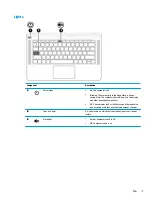
Page 12: ...inger gestures to move the pointer or activate items on the screen 2 Left TouchPad button Functions like the left button on an external mouse 3 Right TouchPad button Functions like the right button on an external mouse 6 Chapter 2 External component identification ...

Page 13: ...uter shuts off power to the display and other unneeded components Off The computer is off or in Hibernation Hibernation is a power saving state that uses the least amount of power 2 Caps lock light On Caps lock is on which switches the key input to all capital letters 3 Mute light Amber Computer sound is off Off Computer sound is on Top 7 ...

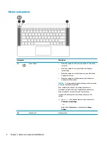
Page 14: ...ernation CAUTION Pressing and holding down the power button results in the loss of unsaved information If the computer has stopped responding and shutdown procedures are ineffective press and hold the power button down for at least 5 seconds to turn off the computer To learn more about your power settings see your power options Type power in the taskbar search box and then select Power and sleep s...

Page 15: ...used system functions when pressed in combination with the esc key or one of the action keys 3 Windows key Opens the Start menu NOTE Pressing the Windows key again will close the Start menu 4 Action keys Execute frequently used system functions NOTE On select products the f5 action key turns the keyboard backlight feature off or on Top 9 ...

Page 16: ... the screen image from the computer display to the monitor display to a simultaneous display on both the computer and the monitor Turns the keyboard backlight off or on NOTE To conserve battery power turn off this feature Plays the previous track Starts pauses or resumes playback Plays the next track Decreases speaker volume incrementally while you hold down the key Increases speaker volume increm...

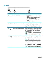
Page 17: ...ower to the computer and can provide video or high resolution display output These ports can also charge products such as cell phones laptops tablets and MP3 players even when the computer is off NOTE Your computer may also support a Thunderbolt docking station NOTE Adapters purchased separately may be required 4 Audio out headphone Audio in microphone combo jack Connects optional powered stereo s...

Page 18: ... to cool internal components NOTE The computer fan starts up automatically to cool internal components and prevent overheating It is normal for the internal fan to cycle on and off during routine operation 12 Chapter 2 External component identification ...

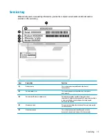
Page 19: ...meric identifier that is unique to each product 3 Part number Product number p n This number provides specific information about the product s hardware components The part number helps a service technician to determine what components and parts are needed 4 Warranty period This number describes the duration of the warranty period for the computer 5 Model description This is the alphanumeric identi...

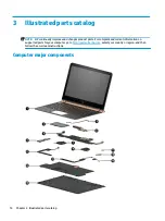
Page 20: ...changes product parts For complete and current information on supported parts for your computer go to http partsurfer hp com select your country or region and then follow the on screen instructions Computer major components 14 Chapter 3 Illustrated parts catalog ...

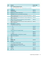
Page 21: ...B of system RAM and the Windows 10 Professional operating system 860825 601 Equipped with an Intel Core i5 6200U 2 30 GHz processor 8 GB of system RAM and a non Windows operating system 860825 001 6 Solid state drive PCIe M 2 NVMe TLC For use in HP Spectre Notebook PC models 1 TB 912677 001 512 GB 855609 001 256 GB 855608 001 For use in HP Spectre Pro13 G1 Notebook PC models 512 GB 900890 001 256 ...

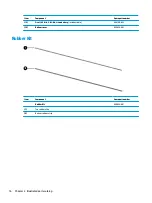
Page 22: ...3 3 cell 45 Wh 3 83 Ah Li ion battery includes cable 844199 855 14 Bottom cover 855626 001 Rubber Kit Item Component Spare part number Rubber Kit 854832 001 1 Top rubber strip 2 Bottom rubber strip 16 Chapter 3 Illustrated parts catalog ...

Page 23: ... in Israel 398063 010 For use in Japan 349756 008 For use in North America 213349 017 For use in the People s Republic of China 286497 015 For use in South Africa 361240 009 For use in Switzerland 213354 015 For use in Taiwan 393313 009 For use in Thailand 285096 014 For use in the United Kingdom 213351 015 Power cord duckhead for use in HP Spectre Notebook PC models For use in the United States 2...

Page 24: ...Component Spare part number HP Business Backpack 718548 001 HP Business Slim Load Top Case 718549 001 18 Chapter 3 Illustrated parts catalog ...

Page 25: ...ns The following sections include some of the considerations that you must keep in mind during disassembly and assembly procedures NOTE As you remove each subassembly from the computer place the subassembly and all accompanying screws away from the work area to prevent damage Plastic parts CAUTION Using excessive force during disassembly and reassembly can damage plastic parts Use care when handli...

Page 26: ...ut down the computer If you are unsure whether the computer is off or in Hibernation turn the computer on and then shut it down through the operating system Before handling a drive be sure that you are discharged of static electricity While handling a drive avoid touching the connector Before removing a diskette drive or optical drive be sure that a diskette or disc is not in the drive and be sure...

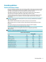
Page 27: ...ve these precautions Keep components in their electrostatic safe containers until you are ready to install them Before touching an electronic component discharge static electricity by using the guidelines described in this section Avoid touching pins leads and circuitry Handle electronic components as little as possible If you remove a component place it in an electrostatic safe container The foll...

Page 28: ...er materials are selected to avoid static charging When grounding is not possible use an ionizer to dissipate electric charges Workstation guidelines Follow these grounding workstation guidelines Cover the workstation with approved static shielding material Use a wrist strap connected to a properly grounded work surface and use properly grounded tools and equipment Use conductive field service too...

Page 29: ...m resistance between the operator and ground To be effective the conductive must be worn in contact with the skin The following grounding equipment is recommended to prevent electrostatic damage Antistatic tape Antistatic smocks aprons and sleeve protectors Conductive bins and other assembly or soldering aids Nonconductive foam Conductive tabletop workstations with ground cords of one megohm resis...

Page 30: ... and or loosened when servicing the computer Make special note of each screw size and location during removal and replacement Bottom cover NOTE The bottom cover spare part kit includes two rear rubber feet one front rubber foot speaker grilles shielding and retention brackets Description Spare part number Bottom cover 855626 001 Before disassembling the computer follow these steps 1 Turn off the c...

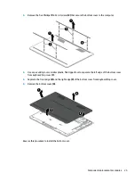
Page 31: ...l or similar plastic flat tipped tool to separate the left edge of the bottom cover from keyboard top cover 1 5 Separate the front edge 2 and the right edge 3 of the bottom cover from keyboard top cover 6 Remove the bottom cover 4 Reverse this procedure to install the bottom cover Component replacement procedures 25 ...

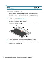
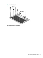
Page 32: ...m cover see Bottom cover on page 24 Remove the battery 1 Disconnect the battery cable from the system board 1 2 Disconnect the speaker cables from the system board 2 and the remove the speaker cables from the routing clips on the sides of the battery 3 3 Remove the six Phillips PM2 0 4 0 screws 1 that secure the battery to the computer 4 Remove the four Phillips PM1 2 2 5 screws 2 that secure the ...

Page 33: ...6 Remove the battery 4 Reverse this procedure to install the battery Component replacement procedures 27 ...

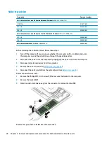
Page 34: ...bernation turn the computer on and then shut it down through the operating system 2 Disconnect the power from the computer by unplugging the power cord from the computer 3 Disconnect all external devices from the computer 4 Remove the bottom cover see Bottom cover on page 24 5 Disconnect the battery cable from the system board see Battery on page 26 Remove the solid state drive 1 Remove the Philli...

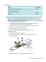
Page 35: ...to restore device functionality and then contact technical support Before removing the WLAN module follow these steps 1 Turn off the computer If you are unsure whether the computer is off or in Hibernation turn the computer on and then shut it down through the operating system 2 Disconnect the power from the computer by unplugging the power cord from the computer 3 Disconnect all external devices ...

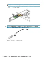
Page 36: ...x terminal 5 Lift the module out of the socket 2 NOTE If the WLAN antennas are not connected to the WLAN module the protective sleeve should be installed on the antenna connectors as shown in the following illustration Reverse this procedure to install the WLAN module 30 Chapter 5 Removal and replacement procedures for Authorized Service Provider parts ...

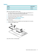
Page 37: ...operating system 2 Disconnect the power from the computer by unplugging the power cord from the computer 3 Disconnect all external devices from the computer 4 Remove the bottom cover see Bottom cover on page 24 5 Remove the battery see Battery on page 26 Remove the speakers 1 Remove the Phillips PM2 0 3 0 screw 1 that secures the right speaker from the computer 2 Remove the speakers 2 and cables R...

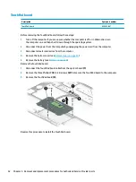
Page 38: ...ing the power cord from the computer 3 Disconnect all external devices from the computer 4 Remove the bottom cover see Bottom cover on page 24 5 Remove the battery see Battery on page 26 Remove the TouchPad board 1 Disconnect the TouchPad board cable from the system board 1 2 Remove the three Phillips PM2 0 3 0 screws 2 that secure the TouchPad board to the computer 3 Remove the TouchPad board 3 R...

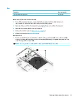
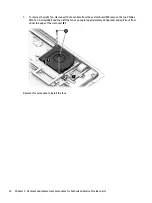
Page 39: ...he power cord from the computer 3 Disconnect all external devices from the computer 4 Remove the bottom cover see Bottom cover on page 24 5 Remove the battery see Battery on page 26 Remove the fans 1 To remove the left fan disconnect the fan cables from the system board 1 remove the two Phillips PM2 0 3 0 screws 2 and then lift the fan at an angle approximately 45 degrees and pull it out from unde...

Page 40: ...ove the two Phillips PM2 0 3 0 screws 2 and then lift the fan at an angle approximately 45 degrees and pull it out from under the edge of the computer 3 Reverse this procedure to install the fans 34 Chapter 5 Removal and replacement procedures for Authorized Service Provider parts ...

Page 41: ... the computer is off or in Hibernation turn the computer on and then shut it down through the operating system 2 Disconnect the power from the computer by unplugging the power cord from the computer 3 Disconnect all external devices from the computer 4 Remove the bottom cover see Bottom cover on page 24 and then remove the following components a Battery see Battery on page 26 b Solid state drive s...

Page 42: ...e of the system board up and forward so you can access the RTC battery cable underneath 2 4 Disconnect the RTC battery cable 3 from the system board 5 Remove the system board 4 Reverse this procedure to install the system board 36 Chapter 5 Removal and replacement procedures for Authorized Service Provider parts ...

Page 43: ... module see WLAN module on page 29 d System board see System board on page 35 Remove the heat sink 1 Following the 1 2 3 sequence stamped into the heat sink remove the three Phillips PM2 0 3 0 screws 1 that secure the heat sink to the system board 2 Remove the heat sink 2 NOTE Due to the adhesive quality of the thermal material located between the heat sink and the system board components it may b...

Page 44: ...Reverse this procedure to install the heat sink 38 Chapter 5 Removal and replacement procedures for Authorized Service Provider parts ...

Page 45: ...s Description Spare part number TouchPad cable 855627 001 WLAN board cable 855628 001 Use the following image to determine proper cable routing 1 WLAN board cable 2 TouchPad cable Component replacement procedures 39 ...

Page 46: ...d top cover with keyboard for use in Italy 855641 061 Display assembly and top cover with keyboard for use in Japan 855641 291 Display assembly and top cover with keyboard for use in Latin America 855641 161 Display assembly and top cover with keyboard for use in Portugal 855641 131 Display assembly and top cover with keyboard for use in Romania 855641 271 Display assembly and top cover with keybo...

Page 47: ...vailable on the HP website Most BIOS updates on the HP website are packaged in compressed files called SoftPaqs Some download packages contain a file named Readme txt which contains information regarding installing and troubleshooting the file Determining the BIOS version To decide whether you need to update Setup Utility BIOS first determine the BIOS version on your computer To reveal the BIOS ve...

Page 48: ...ost recent BIOS update and compare it to the BIOS version currently installed on your computer If the update is more recent than your BIOS version make a note of the date name or other identifier You may need this information to locate the update later after it has been downloaded to your hard drive b Follow the on screen instructions to download your selection to the hard drive Make a note of the...

Page 49: ...lowing order a Connected USB drive NOTE To download the HP PC Hardware Diagnostics UEFI tool to a USB drive see Downloading HP PC Hardware Diagnostics UEFI to a USB device on page 43 b Hard drive c BIOS 3 When the diagnostic tool opens select the type of diagnostic test you want to run and then follow the on screen instructions NOTE If you need to stop a diagnostic test press esc Downloading HP PC...

Page 50: ...let HP automatically detect your product 4 Select your computer and then select your operating system 5 In the Diagnostic section follow the on screen instructions to select and download the UEFI version you want 44 Chapter 7 Using HP PC Hardware Diagnostics UEFI ...

Page 51: ...ckup of the HP Recovery partition on the computer The backup can be used to reinstall the original operating system in cases where the hard drive is corrupted or has been replaced For information on creating recovery media see Creating HP Recovery media select products only on page 45 For information on the recovery options that are available using the recovery media see Using Windows tools on pag...

Page 52: ...to create recovery discs If you use an external optical drive it must be connected directly to a USB port on the computer the drive cannot be connected to a USB port on an external device such as a USB hub If you cannot create DVD media yourself you can obtain recovery discs for your computer from HP See the Worldwide Telephone Numbers booklet included with the computer You can also find contact i...

Page 53: ...o remove the recovery partition to reclaim hard drive space HP Recovery Manager offers the Remove Recovery Partition option For more information see Removing the HP Recovery partition select products only on page 49 Recovering using HP Recovery Manager HP Recovery Manager software allows you to recover the computer to its original factory state by using the HP Recovery media that you either create...

Page 54: ...o start HP Recovery Manager from the HP Recovery partition IMPORTANT For a tablet with a detachable keyboard connect the keyboard to the keyboard dock before beginning these steps select products only 1 Type recovery in the taskbar search box select Recovery Manager and then select HP Recovery Environment or For computers or tablets with keyboards attached press f11 while the computer boots or pre...

Page 55: ...tart the tablet and then quickly hold down the Windows button then select f9 3 Select the optical drive or USB flash drive from which you want to boot 4 Follow the on screen instructions Removing the HP Recovery partition select products only HP Recovery Manager software allows you to remove the HP Recovery partition to free up hard drive space IMPORTANT After you remove the HP Recovery partition ...

Page 56: ...eight 1 0 cm 0 39 in Weight 1 63 kg 3 59 lbs Input power Operating voltage and current 19 5 V dc 2 31 A 45 W 19 5 V dc 3 33 A 65 W 19 5 V dc 4 62 A 90 W 19 5 V dc 6 15 A 120 W 19 5 V dc 7 69 A 150 W Temperature Operating 5 C to 35 C 41 F to 95 F Nonoperating 20 C to 60 C 4 F to 140 F Relative humidity noncondensing Operating 10 to 90 Nonoperating 5 to 95 Maximum altitude unpressurized Operating 15...

Page 57: ... must be approved by an acceptable accredited agency responsible for evaluation in the country or region where the power cord set will be used The power cord sets must have a minimum current capacity of 10 amps and a nominal voltage rating of 125 or 250 V AC as required by the power system of each country or region The appliance coupler must meet the mechanical configuration of an EN 60 320 IEC 32...

Page 58: ...and wall plug must bear a T mark and registration number in accordance with the Japanese Dentori Law The flexible cord must be Type VCT or VCTF 3 conductor 1 00 mm conductor size The wall plug must be a two pole grounding type with a Japanese Industrial Standard C8303 7 A 125 V configuration 4 The flexible cord must be Type RVV 3 conductor 0 75 mm conductor size Power cord set fittings appliance c...

Page 59: ...he battery in general household waste Follow the local laws and regulations in your area for battery disposal HP encourages customers to recycle used electronic hardware HP original print cartridges and rechargeable batteries For more information about recycling programs see the HP Web site at http www hp com recycle 53 ...

Page 60: ...15 display panel product description 1 E esc key identifying 9 F fan removal 33 spare part number 15 33 feet removal 24 spare part number 24 fn key identifying 9 G graphics product description 1 H heat sink removal 37 spare part number 15 37 HP PC Hardware Diagnostics UEFI using 43 HP Recovery Manager correcting boot problems 49 starting 48 HP Recovery media creating 45 recovery 48 HP Recovery par...

Page 61: ...17 security product description 2 service tag 13 serviceability product description 3 solid state drive removal 28 spare part numbers 15 28 solid state drive WLAN module bracket removal 28 Speaker Kit spare part number 15 31 speakers identifying 8 removal 31 spare part number 15 31 specifications 50 storage product description 1 supported discs recovery 46 system board removal 35 spare part number...

Reviews: