background image


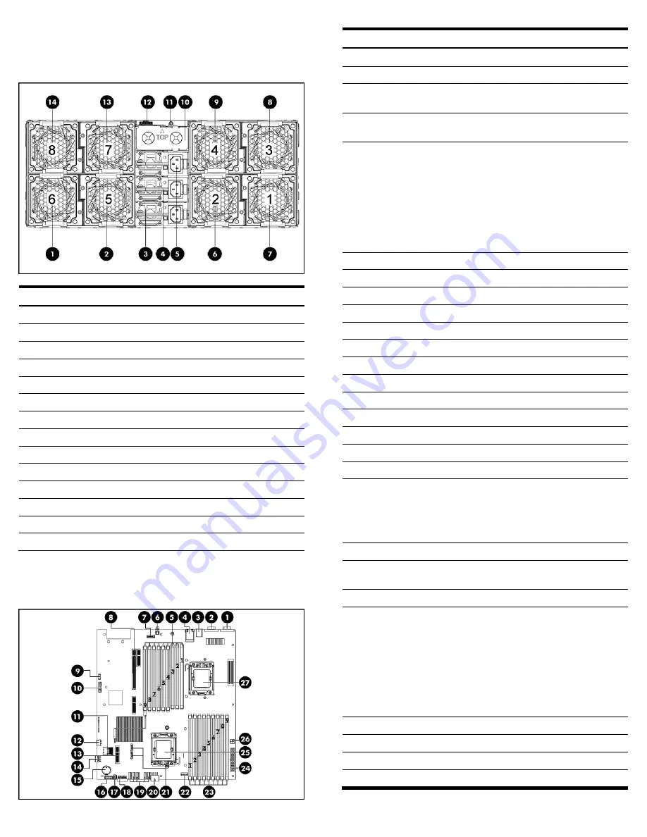
Rear Panel Components 

Figure 2 

Rear panel components of the s6500 chassis with 4 SL160s 

G6 servers 


Item  

Description  

Fan 6 

Fan 5 

Power Supply 1  

Power Supply 2  

Power Supply 3  

Fan 2 

Fan 1 

Fan 3 

Fan 4 

10 

Power Blank 

11 

Chassis UID 

12 

SLAPM(SL Advanced Power Manager) connector 

13 

Fan 7 

14 

Fan 8 

System Board Components 

Figure 3 

System Board components  


Item 

Designator  Description 

J2 

Serial Port (COM1) 

J1 

VGA Port 

J8 

Top: USB 2.0 Port 
Bottom: USB 2.0 Port 

J7 

Top: NIC port2 
Bottom: NIC port1 

J21 
J22 
J79 
J23 
J24 
J78 
J25 
J26 
J77 

CPU2 DIMM 9C slot (from left to right) 
CPU2 DIMM 8F slot 
CPU2 DIMM 7I slot 
CPU2 DIMM 6B slot 
CPU2 DIMM 5E slot 
CPU2 DIMM 4H slot 
CPU2 DIMM 3A slot 
CPU2 DIMM 2D slot 
CPU2 DIMM 1G slot 

SW1 

UID LED/Switch 

J90 

IPMI connector 

J17 

PCIe x16 FH/FL Riser slot1A 

J27 

Jumper 

10 

J29 

TPM connector 

11 

J11 

Mini SAS connector 

12 

J69 

USB 2.0 Port 

13 

J3 

Storage card slot 

14 

J56 

LCD connector 

15 

B1 

CMOS Battery 

16 

J82 

Power supply backplane connector 

17 

J65 

Backplane I

2

C connector 

18 

J42 

Front panel connector 

19 

J67 
J68 
J70 
J62 
J71 

Fan6 connector (from left to right) 
Fan5 connector 
Fan4 connector 
Fan3 connector 
Fan2 connector 

20 

J64 

12V Power connector 

21 

J57 
J58 

SATA5 connector 
SATA6 connector 

22 

J63 

Fan1 connector 

23 

J74 
J43 
J44 
J75 
J45 
J46 
J76 
J47 
J48 

CPU1 DIMM 1G slot (from left to right) 
CPU1 DIMM 2D slot 
CPU1 DIMM 3A slot 
CPU1 DIMM 4H slot 
CPU1 DIMM 5E slot 
CPU1 DIMM 6B slot 
CPU1 DIMM 7I slot 
CPU1 DIMM 8F slot 
CPU1 DIMM 9C slot 

24 

J51 

System power connector 

25 

U73 

Processor 1 socket 

26 

J60 

12V Power connector 

27 

U34 

Processor 2 socket 


Summary of Contents for ProLiant SL160s

Page 1: ...HP ProLiant SL160s G6 Server Installation Instructions Part Number 635239 002 ...

Page 2: ... 1 Front panel components of the s6500 chassis with 4 SL160s G6 servers Item Description 1 Serial port 2 VGA port 3 Top USB 2 0 Port Bottom USB 2 0 Port 4 Top NIC2 Connector Bottom NIC1 Connector 5 Server 1 6 Server 2 7 Power LED Switch 8 Health LED 9 Server 3 10 Server 4 11 UID LED Switch 12 Mgmt NIC ...

Page 3: ...CPU2 DIMM 2D slot CPU2 DIMM 1G slot 6 SW1 UID LED Switch 7 J90 IPMI connector 8 J17 PCIe x16 FH FL Riser slot1A 9 J27 Jumper 10 J29 TPM connector 11 J11 Mini SAS connector 12 J69 USB 2 0 Port 13 J3 Storage card slot 14 J56 LCD connector 15 B1 CMOS Battery 16 J82 Power supply backplane connector 17 J65 Backplane I2 C connector 18 J42 Front panel connector 19 J67 J68 J70 J62 J71 Fan6 connector from ...

Page 4: ... Refer to the HP ProLiant SL160s G6 Server Maintenance and Service Guide available on the HP website http www hp com 7 Install a supported operating system of your choice For detailed procedures refer to the documentation provided by the operating system vendor For a list of operating systems supported by your ProLiant server go to http www hp com go supportos Pre and Post installation Procedures ...

Page 5: ...ion order A B C D E F G H I Memory Socket 3 6 9 2 5 8 1 4 7 NOTES Installation guide for 1P configuration o Follow the sequence of 3A 6B 9C 2D 5E 8F 1G 4H and 7I for the corresponding processor when installing the memory Installation guide for 2P configuration o Follow the sequence of 3A 6B 9C 2D 5E 8F 1G 4H and 7I for the corresponding processor when installing the memory o Install at least one m...

Page 6: ...ocessor has separated from the installation tool carefully re insert the processor in the tool Handle the processor by the edges only and do not touch the bottom of the processor especially the contact area Figure 9 Installing the processor in the installation tool 3 Align the processor installation tool with the socket and install the processor THE PINS ON THE SYSTEM BOARD ARE VERY FRAGILE AND EA...

Page 7: ...red for proper thermal solution Need to install a PCI air baffle before installing the heat sink 1 Align the PCI air baffle facing the hole on the system board and installed it as described in below figure Figure 13 Installing the PCI air baffle Figure 14 Detail information for installing the PCI air baffle To install the heatsink 1 Properly align the heat sink mounting pins to the system board mo...

Page 8: ...he Easy Set up CD Legal notices Copyright 2010 2011 Hewlett Packard Development Company L P The information contained herein is subject to change without notice The only warranties for HP products and services are set forth in the express warranty statements accompanying such products and services Nothing herein should be construed as constituting an additional warranty HP shall not be liable for ...

Reviews: