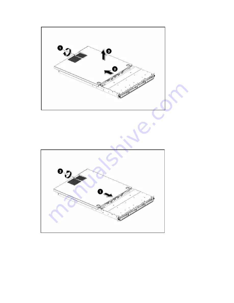
background image


Contents 40 


Figure 9


Removing the Top Cover 


To reinstall the top cover: 

1.


Align the top cover to the chassis and then slide it towards the front panel to position it into 
place. 

2.


Once the cover is attached to the chassis, tighten the captive screw on the rear panel with a T-15 
screwdriver. 

Figure 10

 Reinstalling the Top Cover


Top middle cover 

To remove the top middle cover:  

1.


Loosen the four screws (one on each side of the chassis and two on the top middle cover) that 
secure the top middle cover to the chassis. 

2.


Lift the top middle cover away from the chassis. 


Summary of Contents for ProLiant DL160 Generation 6

Page 1: ...HP ProLiant DL160 Generation 5 Server Maintenance and Service Guide Part number 449871 004 Fourth edition July 2008 ...

Page 2: ...set forth in the express warranty statements accompanying such products and services Nothing herein should be construed as constituting an additional warranty HP shall not be liable for technical or editorial errors or omissions contained herein Intel Xeon and Intel Core are trademarks or registered trademarks of Intel Corporation or its subsidiaries in the United States and other countries ...

Page 3: ...cator 35 Removal and replacement procedures 36 Hardware configuration tools 36 Hardware configuration information 36 Electrostatic discharge information 36 Pre Installation procedure 37 Post installation instructions 37 Server warnings and cautions 37 Symbols on equipment 38 Powering down the server 39 System covers 39 Top cover 39 Top middle cover 40 Drives 42 Cable management 42 Cable connection...

Page 4: ...y 79 Navigating through the setup utility 80 Setup utility menu bar 82 BIOS update 88 Clear CMOS 89 Power On Self Test POST 90 POST error indicators 90 POST errors message definition 90 POST related troubleshooting 93 Physical and operating specifications 94 System unit 94 Index 97 ...

Page 5: ...ipped for next business day delivery Same day or four hour delivery may be offered at an additional charge where geography permits If assistance is required you can call the HP Technical Support Center and a technician will help you over the telephone HP specifies in the materials shipped with a replacement CSR part whether a defective part must be returned to HP In cases where it is required to r...

Page 6: ...SR sont livrées le jour ouvré suivant dans la limite des stocks disponibles et selon votre situation géographique Si votre situation géographique le permet et que vous demandez une livraison le jour même ou dans les 4 heures celle ci vous sera facturée Pour bénéficier d une assistance téléphonique appelez le Centre d assistance technique HP Dans les documents envoyés avec la pièce de rechange CSR ...

Page 7: ...onsegna entro il giorno lavorativo seguente La consegna nel giorno stesso o entro quattro ore è offerta con un supplemento di costo solo in alcune zone In caso di necessità si può richiedere l assistenza telefonica di un addetto del centro di supporto tecnico HP Nel materiale fornito con una parte di ricambio CSR HP specifica se il cliente deve restituire dei componenti Qualora sia richiesta la re...

Page 8: ...alb von vier Stunden gegen einen Aufpreis verfügbar Wenn Sie Hilfe benötigen können Sie das HP technische Support Center anrufen und sich von einem Mitarbeiter per Telefon helfen lassen Den Materialien die mit einem CSR Ersatzteil geliefert werden können Sie entnehmen ob das defekte Teil an HP zurückgeschickt werden muss Wenn es erforderlich ist das defekte Teil an HP zurückzuschicken müssen Sie d...

Page 9: ...al siguiente día laborable Si la situación geográfica lo permite se puede solicitar la entrega en el mismo día o en cuatro horas con un coste adicional Si precisa asistencia técnica puede llamar al Centro de asistencia técnica de HP y recibirá ayuda telefónica por parte de un técnico Con el envío de materiales para la sustitución de componentes CSR HP especificará si los componentes defectuosos de...

Page 10: ...nden voor levering op de eerstvolgende werkdag Levering op dezelfde dag of binnen vier uur kan tegen meerkosten worden aangeboden indien dit mogelijk is gezien de locatie Indien assistentie gewenst is belt u een HP Service Partner om via de telefoon technische ondersteuning te ontvangen HP vermeldt in de documentatie bij het vervangende CSR onderdeel of het defecte onderdeel aan HP moet worden ger...

Page 11: ...o dia útil após o pedido Onde as condições geográficas permitirem a entrega no mesmo dia ou em quatro horas pode ser feita mediante uma taxa adicional Se precisar de auxílio entre em contato com o Centro de suporte técnico da HP para que um técnico o ajude por telefone A HP especifica nos materiais fornecidos com a peça CSR de reposição se a peça com defeito deve ser devolvida à HP Nos casos em qu...

Page 12: ...Contents 12 ...

Page 13: ...Contents 13 ...

Page 14: ...Contents 14 ...

Page 15: ...Contents 15 ...

Page 16: ...47 001 Mandatory1 2 Rail kit 461513 001 Mandatory1 3 Hard drive cage 460019 001 Mandatory1 4 ODD bezel blank 460020 001 Mandatory1 5 Hard drive bezel blank 459187 001 Mandatory1 6 Top middle cover 469239 001 Mandatory1 7 System fan 457873 001 Mandatory1 8 Chassis N A Mandatory1 9 Rail kit 461513 001 Mandatory1 10 Air baffle 460023 001 Mandatory1 11 PCI cage 458749 001 Mandatory1 ...

Page 17: ...eneur Agréé Ces pièces sont identifiées par la mention Non dans le Catalogue illustré 1 Mandatory Obbligatorie Parti che devono essere necessariamente riparate dal cliente Se il cliente ne affida la riparazione ad HP deve sostenere le spese di spedizione e di manodopera per il servizio 2 Optional Opzionali Parti la cui riparazione da parte del cliente è facoltativa Si tratta comunque di componenti...

Page 18: ...g 2 Optional Optioneel Onderdelen waarvoor reparatie door de klant optioneel is Ook deze onderdelen zijn ontworpen voor reparatie door de klant Als u echter HP verzoekt deze onderdelen voor u te vervangen kunnen daarvoor extra kosten in rekening worden gebracht afhankelijk van het type garantieservice voor het product 3 No Nee Sommige HP onderdelen zijn niet ontwikkeld voor reparatie door de klant...

Page 19: ...Contents 19 ...

Page 20: ...12 001 Mandatory1 6 Optical disk drive ODD Mandatory1 SPS DRV 9 5mm DVD ROM m RoHS 436951 001 Mandatory1 SPS DRV 9 5mm COMBO RoHS 462485 001 Mandatory1 7 Memory module Mandatory1 DIMM 1GB PC2 5300 FBD 64Mx8 RoHS 416470 001 Mandatory1 DIMM 512MB PC2 5300 FBD 64MX8 RoHS 416471 001 Mandatory1 8 Processors Intel FC LGA6 with 771 lands Series Optional2 Quad core Intel Xeon 2 0 GHz 1333 MHz 80W 457876 0...

Page 21: ...core Intel Xeon 3 4 GHz 1600 MHz 80W 459737 001 Optional2 Dual core Intel Xeon 3 0 GHz 1333MHz 40W 459739 001 Optional2 Dual core Intel Xeon 2 50 GHz 1333MHz 50W 463719 001 Optional2 9 Processor heat sink 457881 001 Optional2 10 System board 457882 001 Optional2 11 650 W power supply 457626 001 Mandatory1 12 HL HH PCIe x16 LP riser card 460016 001 Mandatory1 13 FL FH PCIe x16 riser card 457871 001...

Page 22: ...e Intel Xeon 2 66 GHz 1333 MHz 80W 457877 001 Optional2 Quad Core Intel Xeon 3 0 GHz 1600 MHz 120W 457880 001 Optional2 Quad Core Intel Xeon 2 33GHz 1333 MHz 50W 459736 001 Optional2 Quad Core Intel Xeon 3 16 GHz 1333 MHz 120W 457879 001 Optional2 Quad Core Intel Xeon 3 0 GHz 1600 MHz 80W 462980 001 Optional2 Quad Core Intel Xeon 2 8 GHz 1600 MHz 80W 459734 001 Optional2 Dual Core Intel Xeon 3 4 G...

Page 23: ...HP deve sostenere le spese di spedizione e di manodopera per il servizio 2 Optional Opzionali Parti la cui riparazione da parte del cliente è facoltativa Si tratta comunque di componenti progettati per questo scopo Se tuttavia il cliente ne richiede la sostituzione ad HP potrebbe dover sostenere spese addizionali a seconda del tipo di garanzia previsto per il prodotto 3 No Non CSR Alcuni component...

Page 24: ...worden vervangen Deze onderdelen worden in de geïllustreerde onderdelencatalogus aangemerkt met Nee 1 Mandatory Obrigatória Peças cujo reparo feito pelo cliente é obrigatório Se desejar que a HP substitua essas peças serão cobradas as despesas de transporte e mão de obra do serviço 2 Optional Opcional Peças cujo reparo feito pelo cliente é opcional Essas peças também são projetadas para o reparo f...

Page 25: ...fore you call HP Technical support registration number if applicable Product serial number Product model name and number Applicable error messages Add on boards or hardware model number and serial number Third party hardware or software model number Operating system type and revision level ...

Page 26: ...es of the HP ProLiant DL160 G5 server Connectors and components Front panel components Figure 1 Front panel components Item Description 1 Thumbscrews for rack mounting 2 Optical disk drive bay 3 Serial number pull tab 4 Two front USB 2 0 ports 5 Unit identification UID LED button 6 System health LED 7 NIC1 LED 8 NIC2 LED 9 Power button with LED indicator bicolor green and amber 10 HDD LED 11 Hard ...

Page 27: ...port for NIC2 4 Captive thumbscrew for top cover 5 Serial port teal 6 Low profile Half length expansion slot 7 Full Height Full length expansion slot 8 T10 T15 wrench 9 Thumbscrew for PCI cage 10 UID LED button 11 VGA port 12 HP LO100i management LAN port 13 Two rear USB 2 0 ports 14 GbE LAN port for NIC1 Management 15 PS 2 keyboard port purple ...

Page 28: ...eyboard port 2 J20 Top LAN port 2 Bottom LAN port 1 3 J15 Top USB 2 0 port Bottom USB 2 0 port 4 J22 Management port 5 P10 Top Serial port Bottom VGA port 6 SW4 UID LED button 7 J52 PCIe slot PCIe x16 link with x16 slot 8 P13 NMI jumper 9 J18 PCIe slot PCIe x16 link with x16 slot 10 XBT1 3V CMOS battery 11 J14 USB 2 0 cable header ...

Page 29: ...ystem fan 2 header 24 P23 5 pin system fan1 header 25 P27 8 pin power connector 26 P26 24 pin power connector 27 P28 4 pin power connector 28 XMM FBD slots Jumpers Password and chassis ID The system board password P36 chassis ID0 P38 and chassis ID1 P39 headers Table 4 describes the jumper settings Table 4 System configuration switch settings Jumper Status P36 On default Off P38 Off default P39 On...

Page 30: ...ponents and operations of the server Front panel LED indicators The front panel LED indicators allow constant monitoring of basic system functions while the server is operating Optical drive activity LED indicator The optical drive has an activity indicator that indicates when the drive is reading media Figure 4 Optical drive activity LED indicator Activity states for the optical drive are as foll...

Page 31: ... Figure 5 Power LED Indicator location Table 5 Power system health LED indicator status Component Status Description Power system health LED indicator Steady green The server is operating normally Steady amber The server is system off or in hibernation with A C power Off The server is system off without A C power ...

Page 32: ... is not a member of any RAID volumes or the drive is configured but is in a replacement or failed state for at least one volume that it is a member of or the drive is a spare drive that is inactive or has been activated but has not been rebuilt The drive is not rebuilding The drive is not a member of a volume undergoing capacity expansion or RAID migration Solid green The drive is a member of a RA...

Page 33: ...ty expansion or RAID migration Flashing green 1 Hz 50 duty cycle override drive activity output The drive is rebuilding The drive is a member of a volume undergoing capacity expansion or RAID migration 2 Drive Online Error LED indicator Off The drive is not in a failed state The drive is not selected unit identification Solid blue The drive is not in a failed state The drive is selected unit ident...

Page 34: ...cation Table 7 LAN LED indicator states Item Component Status Description 1 LAN activity status LED indicator Flashing green Ongoing network data activity Off No network data activity or no connection 2 LAN network speed LED indicator Steady green The LAN connection is using 10Mbps 100 Mbps link Steady amber The LAN connection is using a GbE link Off No connection ...

Page 35: ...ator The system board contains one LED indicator for use during troubleshooting operations Figure 8 System board LED indicator Table 8 System board LED indicator Item Component Status Description 1 LED indicator Green System state show ...

Page 36: ...ollowing tools T 10 T 15 screwdrivers Flat blade screwdriver The following references and software tools will assist with the hardware configuration HP ProLiant DL160 G5 Server Support CD IPMI Event Log Diagnostics Software Hardware configuration information Electrostatic discharge information An electrostatic discharge ESD can damage static sensitive devices or micro circuitry Proper packaging an...

Page 37: ... configuration process read through the entire installation removal procedure first and make sure you understand them before you before you begin Post installation instructions Observe the following items after installing or removing a server component 1 Be sure all components are installed according to the described step by step instructions 2 Reinstall the rear cage air baffle peripherals and sy...

Page 38: ...en for any reason WARNING To reduce the risk of injury from electric shock hazards do not open this enclosure This symbol on an RJ 45 receptacle indicates a network interface connection WARNING To reduce the risk of electric shock fire or damage to the equipment do not plug telephone or telecommunications connectors into this receptacle This symbol indicates the presence of a hot surface or hot co...

Page 39: ... output is disabled Standby does not completely disable or remove power from the system 3 Disconnect the AC power cord from the AC outlet and then from the server 4 Be sure that the power LED indicator is turned off and that the fan noise has stopped 5 Disconnect all external peripheral devices from the server System covers The top cover and top middle cover are both detachable You need to remove ...

Page 40: ...nce the cover is attached to the chassis tighten the captive screw on the rear panel with a T 15 screwdriver Figure 10 Reinstalling the Top Cover Top middle cover To remove the top middle cover 1 Loosen the four screws one on each side of the chassis and two on the top middle cover that secure the top middle cover to the chassis 2 Lift the top middle cover away from the chassis ...

Page 41: ... reinstall the top middle cover 1 Align the top middle cover to the chassis 2 Fasten the four screws one on each side of the chassis and two on the top middle cover to securing the top middle cover to the chassis Figure 12 Reinstalling the top middle cover ...

Page 42: ...ses may damage the wires Some flat ribbon cables come pre folded Never change the folds on these cables Do not sharply bend any cable A sharp bend can break the internal wires Never bend a SATA data cable tighter than a 30 mm 1 18 in radius Never crease a SATA data cable Do not rely on components like the drive cage power supply or system cover to push cables down into the chassis The next steps i...

Page 43: ...ug into For more detailed information about system board components see System board components Table 10 Cable Connections Cable To System Board Designator 18 Pin Front Panel Connector Front panel P17 SATA 4 Connector SATA 4 P33 SATA 3 Connector SATA 3 P32 SATA 2 Connector SATA 2 P31 SATA 1 Connector SATA 1 P30 External HDD LED Connector External HDD LED P17 Front USB 2 0 Cable Header USB 2 0 P37 ...

Page 44: ...our bays for 3 5 inch hard disk drives and one drive bay for an optical media drive Figure 14 System drive bays Item Description 1 Optical Media Device Bay 2 3 5 Inch Hard Disk Drive Bays four The HDD bays support both non hot plug and hot plug SATA drives as well as hot plug SAS drives ...

Page 45: ...nd all the peripherals connected to it 2 Unplug all external cables and AC power cords If necessary label each one to expedite reassembly 3 Remove unit from rack and place on a flat surface 4 Remove the top cover 5 Remove the top middle cover To remove the bezel blank 1 Pull the bezel blank out of the carrier CAUTION Do not discard the bezel blank If the optical drive is removed in the future you ...

Page 46: ... To install the optical drive 1 Slide the optical drive assembly into the chassis Figure 17 Installing the optical drive 2 Remove the top middle cover and connect the IDE data and power cables to their corresponding connectors on the optical drive ...

Page 47: ...2 Uplift the spring latch securing the optical drive carrier to the chassis 3 Push the optical drive toward the front of the unit 4 Pull the optical drive out of the chassis Figure 19 Removing the optical drive IMPORTANT If you removed an optical drive without plans of installing a new one you must reinstall the blank to maintain proper system airflow ...

Page 48: ...ives or SATA hard drives in the server Hard drives installed in the server are labeled from Device 1 to Device 4 from left to right when viewed from the front of the server Figure 20 Hard drive bays configuration Item Description 1 1st SAS SATA hard drive 2 2nd SAS SATA hard drive 3 3rd SAS SATA hard drive 4 4th SAS SATA hard drive ...

Page 49: ...er system airflow 2 Install a hard drive a Push the hard drive assembly into the drive bay until it stops b Press the HDD carrier latch inward until it clicks Figure 22 Installing the hot plug hard drive assembly To remove hard drive 1 Press the hard disk carrier button to release the ejector lever 2 Use the HDD carrier latch to pull the drive out of the cage Make sure to support the drive when pu...

Page 50: ...non hot plug hard drive 1 Loosen four screws from the top part of the carrier 2 Put the non hot plug hard drive disk into the carrier 3 Fasten the HDD to the carrier using the screws two on each side Figure 24 Installing the non hot plug hard drive disk into the carrier ...

Page 51: ...ve assembly into the drive bay until it stops 3 Fasten the screw with the T 15 wrench provided to secure the hard drive to the chassis 4 Connect the cabling from the HDD backplane to the drive using the cables provided Figure 26 Installing the non hot plug hard drive assembly To remove the non hot plug hard drive 1 Loosen the screw with the T 15 wrench provided 2 Pull the hard drive assembly out o...

Page 52: ... hot plug hard drive assembly To remove a non hot plug hard drive disk from the carrier 1 Loosen the four screws on the carrier two on each side 2 Lift the hard drive from the carrier Figure 28 Removing the non hot plug hard drive assembly ...

Page 53: ...ane The following figures show the front and back side of the backplane Figure 29 Backplane connectors component side Item Description 1 Screw Holes 2 LED indicators 3 Headers for Hard Drive Figure 30 Backplane connectors solder side ...

Page 54: ...an AC power source is connected This voltage is present even when the main power switch is in the off position To remove the backplane 1 Remove all drives out of the drive bays Refer to the Hard drives sections in this chapter for detailed procedures Figure 31 Removing the hot plug hard drives 2 Remove the top cover 3 Remove the top middle cover 4 Remove the backplane a Remove all cables including...

Page 55: ...1 Orient the backplane so that the notches on the board align with the hook on the drive cage and press the board down until it clicks into place 2 Secure the backplane with two screws Figure 33 Installing the backplane 3 Install all cables including optical drive cables ...

Page 56: ...ts from processor 0 and provides a processor failure message The processor socket supports Quad Core Intel Xeon processor CAUTION It is recommended to use processors of same speeds or cache sizes to prevent possible server malfunction Figure 34 Processor locations Item Description 1 Processor 1 2 Processor 0 WARNING To reduce the risk of personal injury from hot surfaces allow the heat sink and th...

Page 57: ...face Figure 36 Removing heat sink assembly IMPORTANT If the heat sink has been removed for any reason on a previously installed processor it is critical that you apply more thermal interface material to the integrated heat spreader on the processor to ensure proper thermal bonding between the processor and the heat sink To remove a processor 1 Disengage the load lever 2 Lift the retention plate to...

Page 58: ...mal interface material To apply the thermal grease compound 1 Use a clean cloth dipped in rubbing alcohol to clean the contact surface on the heat sink and on the new processor Wipe the contact surfaces several times to make sure that no particles or dust contaminants are evident 2 Apply the thermal grease compound to the CPU contact surface to brush a thin coat to cram the gap Neither too thick n...

Page 59: ...sink with excessive grease can also cause the grease to spread over the processor pins or the system board base which can cause electrical shorts that damage the system To install the new processor 1 Insert the processor into the socket using the key on the processor CAUTION With the load lever and the retention plate disengaged hold the processor by its edges and align it over the empty processor...

Page 60: ...ecified for the HP ProLiant DL160 G5 server To install the heat sink 1 Properly align the heat sink mounting pins to the system board mounting holes 2 Tighten the mounting pins clockwise to secure the heat sink connection to the system board Figure 40 Installing the heat sink To install the air baffle 1 Gently place in the air baffle ...

Page 61: ...es when adding or replacing memory modules For 2P system both physical processors must be of the same type and speed Use 667 DDR2 4 0 GHz FBD Fully Buffered DIMM Supported DIMM capacity 512 MB 1 GB 2 GB and 4 GB Supported configuration Two DIMMs Identical model in XMM1 XMM3 Four DIMMs Identical pair in XMM1 XMM3 and the other identical pair in XMM5 XMM7 Eight DIMMs Identical pair in XMM1 3 XMM5 7 ...

Page 62: ...dule upward to remove it from the slot Figure 43 Removing a memory module CAUTION Place the memory module on a static dissipating work surface or inside of an anti static bag To install a memory module 1 Align the notch on the bottom edge of the module with the keyed surface of the DIMM slot and then press the module fully into the slot 2 Firmly press the holding clips inward to secure the memory ...

Page 63: ...ure 45 System board PCI expansion slots Item Component Designator Component Function 1 J52 Low Profile PCIe slot Support a PCIe or PCI X riser card 2 J18 Full Length Full Height PCIe slot Support a PCIe or PCI X riser card PCI riser card expansion slots The two PCI Express riser cards attached to the PCI cage convert the functionality of the system board expansion slots to the slots positioned at ...

Page 64: ...CIe riser card connector location Single Slot PCIe Riser card x16 link with x16 slot PCI cage To remove the PCI cage NOTE Disconnect all cables connecting an existing expansion board to the system board 1 Loosen the two captive screws that secure the PCI cage to the chassis 2 Lift the PCI cage away from the chassis ...

Page 65: ...ted expansion boards that meet the following specifications Compliance PCI Express x16 PCI X available only when the optional PCI X riser board is installed Form Factor Low profile Full Height Full Length To remove the PCIe Riser card 1 Loosen the two screws securing the riser card to the PCI cage 2 Push the riser card down and away from the PCI cage ...

Page 66: ...ard 1 Figure 50 Removing the PCIe riser card 2 To install the PCIe Riser card 1 Align the two riser card slots to the standoff on the PCI cage and then push the card up 2 Install and tighten the two screws that secure the riser card to the PCI cage ...

Page 67: ...r card 2 To remove the slot cover 1 Loosen the screw s that secure s the slot cover s to the chassis 2 Remove the slot cover s on the PCI cage CAUTION Do not discard the slot cover If the expansion board is removed in the future the slot cover must be reinstalled to maintain proper cooling ...

Page 68: ... 54 Removing the slot cover 2 To install the PCI card 1 Slide the expansion board into the slot aligning the board with its matching connector Firmly press the board to seat it properly on the slot 2 Tighten the screw that secures the card to the PCI cage ...

Page 69: ...the open expansion slot b Press the PCI card straight down into the expansion slot on the system board 2 Align the PCI cage to the system board expansion slot and then press it down to ensure full connection to the system board 3 Tighten the two captive screws to secure the PCI cage to the chassis Figure 56 Reinstalling the PCI cage with PCI card ...

Page 70: ...ery location WARNING Note the following reminders when replacing the system battery Replace the battery with the same type as the battery recommended by HP Use of another battery may present a risk of fire or explosion A risk of fire and chemical burn exists if the battery is not handled properly Do not disassemble crush puncture or short external contacts or expose the battery to temperatures hig...

Page 71: ...ts holder squeeze the metal clamp that extends above one edge of the battery When the battery pops up lift it out 2 To insert the new battery slide one edge of the replacement battery under the holder s lip with the positive side up Push the other edge down until the clamp snaps over the other edge of the battery Figure 59 Replacing the battery System board removal and replacement procedure To rem...

Page 72: ... the system board I O connectors to their openings and slide the system board into place The nine screw holes on the chassis should align with the system board 2 Fasten the nine screws on the system board to secure the system board to the chassis Figure 61 Installing the system board ...

Page 73: ...reduce the risk of personal injury from electric shock hazards and or damage to the equipment Installation of power supply units should be referred to individuals who are qualified to service server systems and are trained to deal with equipment capable of generating hazardous energy levels DO NOT open the power supply unit There are no serviceable parts inside it To remove the power supply 1 Loos...

Page 74: ... to the right location next to the motherboard 2 Align the screw holes on the power supply with the screw holes on the chassis one on the top of the power supply others on the sides 3 Fasten the power supply to the chassis using the screws that just been loosened Figure 64 Installing the non hot plug power supply ...

Page 75: ...ndle 3 Slide the hot plug power supply out of the power supply bay Figure 66 Removing the hot plug power supply To replace the hot plug power supply 1 Align the hot plug power supply cage connector with the open slot of power supply and slide the hot plug power supply into the power supply bay until it snaps into place 2 Snap the latch cover over port colored handle Latch cover only installs one w...

Page 76: ...ter wall The figure below identifies the system fans by their device number and shows their corresponding cable connections Figure 68 System fan connections Device number Connector System fan 1 P23 on the system board System fan 2 P25 on the system board System fan 3 P21 on the system board System fan 4 P19 on the system board ...

Page 77: ...se a default system fan becomes defective To remove the system fan 1 Disconnect the fan cable from its corresponding board connector 2 Release the fan cable from the cable clip 3 Lift the system fan away from the chassis Figure 69 Removing the system fan To replace the system fan 1 Put the fan cable through the system fan bracket Secure the cable with the cable clip on the chassis 2 Hold the syste...

Page 78: ...Contents 78 Figure 70 Installing the system fan ...

Page 79: ...ion PXE boot and much more Initialize hardware at boot up using POST routines During power on or warm reset the BIOS perform Power On Self Test POST routines to test system components to allocate resource for various hardware devices and to prepare the system to boot to various operating systems BIOS setup utility The HP server BIOS Setup Utility is used to configure five primary menu selections M...

Page 80: ...s user configurable Grayed out parameters are not user configurable for one of the following reasons The field value is auto configured or auto detected The field value is informational only The field is password protected Enter To select a field value or display a submenu screen Displays more option for items marked with Esc If you press this key On one of the primary menu screens the Exit menu d...

Page 81: ...Contents 81 Figure 71 Setup utility general help screen Press F1 to get the general help message box ...

Page 82: ...View BIOS ID and BIOS version View CPU type CPU speed CPU physical count information View System memory size View System serial number View MAC address for the embedded NIC Set Server Asset Tag Set system time and date Set boot features Enable or Disable the BIOS summary display Enable or Disable Bootup Num Lock Set restore on AC power loss options such as last state power off and power on If BIOS...

Page 83: ...iguration and settings IDE Configuration Configure ATA IDE IO Device Configuration Configure Embedded Serial port ACPI Configuration Section for Advanced ACPI configuration IPMI Configuration IPMI Configuration including server monitoring and event log USB Configuration Configure the USB support Event Log Configuration Mark as read clear or View Event Log Remote Access Configuration Configure Remo...

Page 84: ...Contents 84 Figure 74 IPMI submenu of the BIOS setup utility If use low voltage CPU and no PCI full length full height slot populated the 6th fan is nonsensical ...

Page 85: ...nu of the BIOS setup utility Use this menu to configure the boot priority Set boot device priority By default the server searches for boot devices in the following order 1 CD DVD Drives 2 Removable Devices 3 Hard Disk Drives 4 Network Drives ...

Page 86: ...Contents 86 Security menu Figure 76 Security menu of the BIOS setup utility 1 ...

Page 87: ...dministrator password 1 In the Security screen select a set password field Change Administrator Password and then press Enter 2 Type a new password in the Enter New Password box 3 The password may consist of up to six characters Alphanumeric characters A Z a z 0 9 are recommended to avoid system error 4 Retype the password to verify the first entry and then press Enter 5 Press F10 to close the Set...

Page 88: ...ss Esc key Discard Changes Discard any changes you have made You can also press F7 key Load Optimal Defaults Load the factory default values for all items You can also press F9 key BIOS update Perform the steps below to update BIOS 1 Download the Smart Component SPxxxxx exe to a directory on your hard drive 2 Execute SPxxxxx exe and followed with direction to complete the steps ProLiant Flash Upda...

Page 89: ...Setup Utility have caused error messages to be unreadable To clear CMOS 1 Perform the Pre Installation procedure 2 If necessary remove any accessory boards or cables that prevent access to the system configuration switch 3 Locate the system configuration button SW6 on the system board 4 Press the button AC power must not be connected 5 Perform the Post installation instructions 6 During POST press...

Page 90: ...or indicators When POST detects a system failure it displays a POST error message POST errors message definition Whenever a non fatal error occurs during POST an error message describing the problem appears onscreen These error messages are displayed in normal video white text on black background and show the details of the error The following is an example of a POST error message 012 CMOS Date Ti...

Page 91: ...ld not be properly initialized by the BIOS This message is typically displayed when the BIOS is trying to detect and configure IDE ATAPI devices in POST 04F Secondary Master Hard Disk Error The IDE ATAPI device configured as Secondary Master could not be properly initialized by the BIOS This message is typically displayed when the BIOS is trying to detect and configure IDE ATAPI devices in POST 05...

Page 92: ...t password more than three times then display this error information and continue to boot There are two password checked failed 05E for setup password Checking NVRAM Update Failed BIOS could not write to the NVRAM block This message appears when the FLASH part is malfunctioning Operating system not found Operating system cannot be located on any of the boot drives Verify that the priority boot dri...

Page 93: ...e POST failure is during a routine boot up check the following All external cables and power cables should be firmly plugged in The power outlet to the server should be connected and works correctly The server and monitor are both turned on The bicolour status LED indicator on the front panel must be lit up green The monitor s contrast and brightness settings are correct All internal cables are pr...

Page 94: ...grated into Pilot I O subsystem One PCIe x16 links with x16 slot One PCIe x16 links with x16 slot Memory Eight 667 DDR2 4 0 GHz FBD up to 32GB Default media storage One half height IDE CD ROM drive SATA hard drive Optional media storage One slim ODD drive bay for CD ROM DVD ROM drive four non hot plug SATA hard drives or SAS devices Four bays hot plug HDD cage for SAS or SATA drives I O ports PS2 ...

Page 95: ...01 7 F Relative humidity Operating Non operating Storage 10 to 90 non condensing 5 to 95 5 to 95 Altitude Operating Non operating 0 to 3049 meters 0 to 10 000 ft 0 to 9146 meters 0 to 30 000 ft Thermal output maximum operating Acoustic emissions Normal configuration 392 W hr c LWad 6 7 Bels operating at room temperature LWad 6 7 Bels Idle at room temperature Table 16 Non Hot Plug Power Supply Spec...

Page 96: ...r Supply Specifications Item Description Dimensions H x W x D 40 5 mm x 86 4 mm x 190 5 mm Weight approximate 1 1 kg Input requirements Rated input voltage Normal line voltage 90 VAC to 264 VAC 100 VAC to 120 VAC 200 VAC to 240 VAC Line frequency 50 60 Hz Rated input current 7 8 10 A BTU rating N A Power supply output power Rated steady state power Maximum peak power 1200W N A Temperature range Op...

Page 97: ...Setup Utility 78 BIOS software 78 BIOS update 87 clear CMOS 88 POST 89 drive bay configuration 44 drives back plane 53 cable connections 43 cable management 42 drive bay configuration 44 hard drives 47 optical media drive 45 E electric shock symbol 38 warning 37 environmental specifications 94 exploded view mechanical components 16 system components 20 21 F front panel components 26 H hard drive i...

Page 98: ...35 M mechanical parts illustrated 16 memory module installing 62 module orientation 63 removing 62 memory module spare part number 20 22 N non hot plug hard drive installing 50 O onboard controllers LAN 93 storage controller 93 optical carrier installing 46 spare part number 16 optical drive activity indicator 30 removing 47 P PCI cage installing 69 removing 64 PCI cage spare part number 16 PCI ca...

Page 99: ...rity menu 85 slot cover removing 67 specifications physical and operating 93 storage controller 93 symbols on equipment 38 system battery replacing 71 system board components 28 dimensions 94 LED 35 platform 94 replacing 72 spare part number 21 22 system covers top cover 39 system fan removing 76 replacing 77 spare part number 20 22 system LEDs See status LEDs system parts illustrated 20 21 system...

Reviews: