HP ProLiant BL p-Class User Manual Download Page 8


CAUTION:  Properly ground yourself before beginning any installation procedure. 
Electrostatic discharge can damage electronic components. For more information 
about electrostatic discharge, refer to the setup and installation guide. 


CAUTION:  Disconnect the local I/O cable when not in use. The port and connector 
do not provide a permanent connection. Rear iLO connector performance degrades 
when the local I/O cable is in use, even when the iLO connector on the cable is not in 
use. 

Using the Diagnostic Cable or the Local I/O Cable for 
Configuration or Diagnostic Procedures 

Use either the diagnostic cable or the local I/O cable to perform some server blade 
configuration and diagnostic procedures. Depending on the model, the server blade 
will have either a diagnostic port or an I/O port. The I/O port only accepts the local 
I/O cable and the diagnostic port only accepts the diagnostic cable. If the server blade 
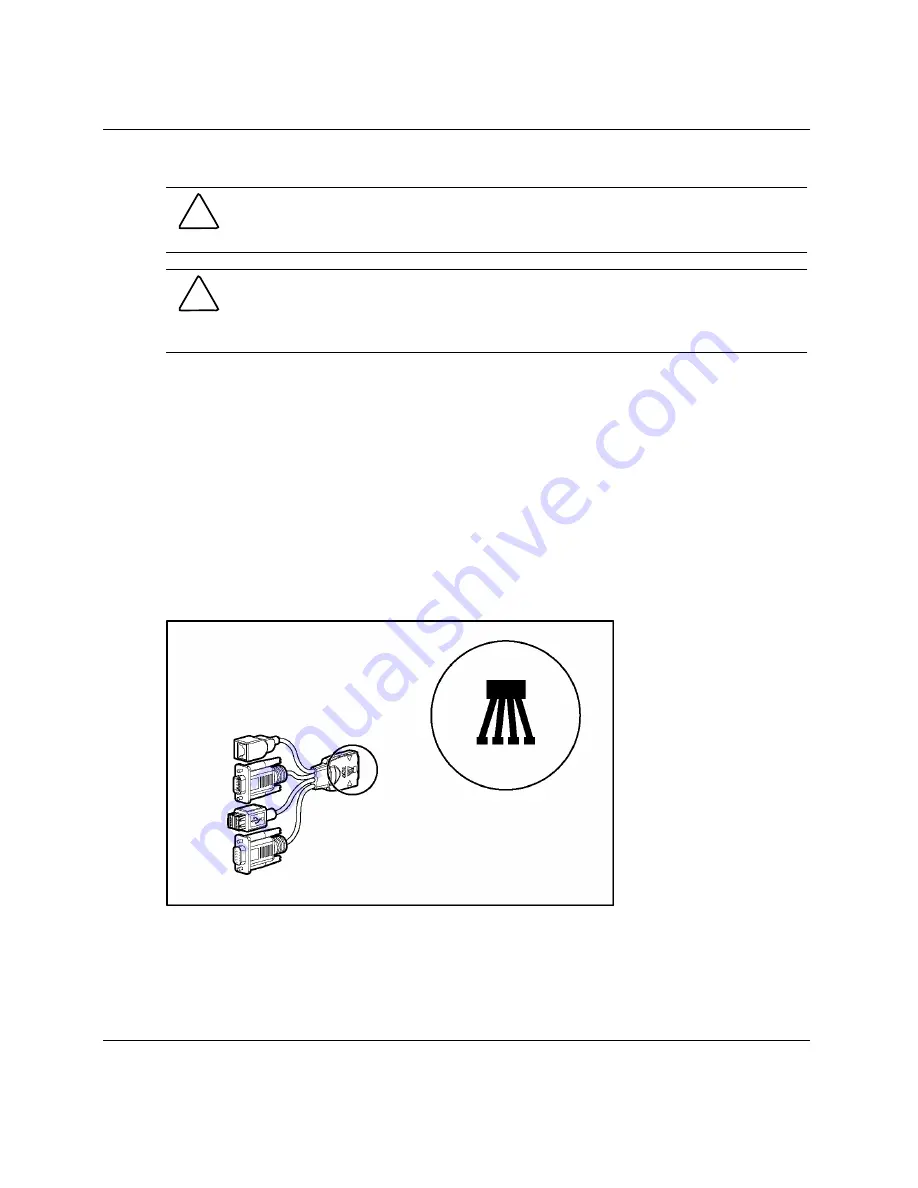
has an I/O icon next to the port on the front of the server blade, use the local I/O 
cable. If the port has no icon, use the diagnostic cable. Refer to Figure 2 to identify 
the I/O icon. 


Figure 2:  Local I/O cable with large view of the I/O icon 

8 

HP ProLiant BL p-Class System Diagnostic Station User Guide 


Summary of Contents for ProLiant BL p-Class

Page 1: ...HP ProLiant BL p Class System Diagnostic Station User Guide Part Number 230859 004 April 2004 Fourth Edition ...

Page 2: ...d trademark of Sun Microsystems Inc Hewlett Packard Company shall not be liable for technical or editorial errors or omissions contained herein The information in this document is provided as is without warranty of any kind and is subject to change without notice The warranties for HP products are set forth in the express limited warranty statements accompanying such products Nothing herein should...

Page 3: ... Storage Area 13 Client PC Requirements 14 Server Blade 14 Preparing the Server Blade for Connection 15 Cabling the Diagnostic Station to a Server Blade 15 Powering Up the Server Blade 29 iLO Guidelines for Accessing the Server Blade 30 GbE Interconnect Switch 32 Regulatory Compliance Notices 32 Regulatory Compliance Identification Numbers 32 Federal Communications Commission Notice 32 Modificatio...

Page 4: ...BSMI Notice 34 4 HP ProLiant BL p Class System Diagnostic Station User Guide ...

Page 5: ...nt provides instructions for cabling the diagnostic station to an HP ProLiant BL p Class server blade to enable out of rack communication with the server blade HP ProLiant BL p Class System Diagnostic Station User Guide 5 ...

Page 6: ...pending on the server blade you are using Figure 1 Diagnostic station kit contents Table 1 Diagnostic Station Kit Contents Item Description 1 Diagnostic station 2 VHDM converter 3 Data transfer cable continued 6 HP ProLiant BL p Class System Diagnostic Station User Guide ...

Page 7: ...WARNING To reduce the risk of shock or injury from high current electrical energy do not remove the server blade access panel while the server blade is connected to the diagnostic station Powering the server blade with the access cover removed is a service operation and must only be performed by trained service personnel WARNING To reduce the risk of shock or injury from high current electrical en...

Page 8: ...r the Local I O Cable for Configuration or Diagnostic Procedures Use either the diagnostic cable or the local I O cable to perform some server blade configuration and diagnostic procedures Depending on the model the server blade will have either a diagnostic port or an I O port The I O port only accepts the local I O cable and the diagnostic port only accepts the diagnostic cable If the server bla...

Page 9: ...ector Name Connector Description Diagnostic cable top 1 Server blade connector Provides a direct connection to the server blade 2 iLO 10 100 Ethernet RJ 45 connector 1 Provides a 10 100 Ethernet RJ 45 connector through which you can access the server blade with the iLO Remote Console and a client PC 1 A standard Ethernet cable can be used with the RJ 45 connector for a direct cable connection cont...

Page 10: ...de 7 Serial connector Requires a null modem serial cable and enables trained personnel to perform advanced diagnostic procedures 8 iLO 10 100 Ethernet RJ 45 connector 1 Provides a 10 100 Ethernet RJ 45 connector through which you can access the server blade with the iLO Remote Console and a client PC 9 Server blade connector Provides a direct connection to the server blade 1 A standard Ethernet ca...

Page 11: ... some ProLiant p Class products Power up a server blade or interconnect switch Observe external LEDs Test NIC activity Configure a server blade or interconnect switch Load software on a server blade or interconnect switch Test a server blade or interconnect switch after installing an option or upgrade Diagnose a server blade or interconnect switch problem using iLO or connecting directly to the se...

Page 12: ...rconnect switch Diagnostic Station Components Use Figure 4 and Table 3 to identify diagnostic station components Figure 4 Diagnostic station components Table 3 Diagnostic Station Components Item Component Description 1 RJ 45 connector for NIC 1 PXE default and data 2 RJ 45 connector for NIC 2 Data 3 RJ 45 connector for NIC 3 Data 4 RJ 45 connector for NIC 4 iLO continued 12 HP ProLiant BL p Class ...

Page 13: ...port 9 NIC LEDs 10 Power On Off button 11 Power and health LED This component does not apply to the ProLiant BL30p server blade Accessing the Cable Storage Area To access the cable storage area 1 Turn the locking latch clockwise 1 2 Pull down the cable storage area access door 2 Figure 5 Accessing the cable storage area HP ProLiant BL p Class System Diagnostic Station User Guide 13 ...

Page 14: ...or TCP IP networking and an IP address compatible with one of the following iLO diagnostic port static IP address 192 168 1 1 mask 255 255 255 0 Assigned DHCP or static IP address Any of the following Java Runtime Environment versions 1 3 1_02 1 3 1_07 1 3 1_08 1 4 1 for Windows users only 1 4 2 for Linux users only Access the Java Runtime Environment versions at http java sun com products archive...

Page 15: ...ethod is recommended for installing an operating system on a server blade The connection can be made in one of two ways With a client PC Connect to iLO using either the diagnostic port or the I O port on the front of the server blade This is a direct one to one connection using the diagnostic cable or the local I O cable from the client PC to iLO without any hub switch networking hardware The iLO ...

Page 16: ...erform server blade configuration or advanced troubleshooting In this method the client PC is connected to the iLO using a hub switch and the network connections of the diagnostic station The iLO default configuration enables the server blade to obtain its IP address from a DHCP server Using the Direct Cabling Method with a Client PC NOTE Items in addition to those provided with the diagnostic sta...

Page 17: ...ad the DC power cord for a server blade or blade sleeve through the opening in the VHDM converter 1 2 Snap the cord into place in the VHDM converter 2 Figure 6 Threading the DC power cord through the VHDM converter HP ProLiant BL p Class System Diagnostic Station User Guide 17 ...

Page 18: ...the left side are properly aligned 4 Tighten the thumbscrew to secure the VHDM converter to the server blade 2 or the blade sleeve 5 Insert the DC power cord into one of the diagnostic station DC power connectors 3 Figure 7 Attaching the VHDM converter and connecting the DC power cord 18 HP ProLiant BL p Class System Diagnostic Station User Guide ...

Page 19: ...VHDM converter on the server blade 1 or the blade sleeve 7 Connect the other end of the data transfer cable to the diagnostic station 2 Figure 8 Connecting the data transfer cable HP ProLiant BL p Class System Diagnostic Station User Guide 19 ...

Page 20: ...ocal I O cable is in use even when the iLO connector on the cable is not in use a Connect the network cable with RJ 45 connectors to the client PC 1 b Connect the other end of the RJ 45 network cable to the diagnostic cable 2 The kernel debug connector can remain unused c Connect the diagnostic cable to the diagnostic port on the front of the server blade 3 d Go to step 10 Figure 9 Connecting the ...

Page 21: ...en when the iLO connector on the cable is not in use a Connect the network cable with RJ 45 connectors to the client PC 1 b Connect the other end of the RJ 45 network cable to the local I O cable 2 The remaining connectors can remain unused c Connect the local I O cable to the I O port on the front of the server blade 3 Figure 10 Connecting the server blade to a client PC using the local I O cable...

Page 22: ...ver blade the server blade must be installed in the left slot of the blade sleeve on a flat surface Figure 11 Connecting the ProLiant BL30p server blade to a client PC using the local I O cable 22 HP ProLiant BL p Class System Diagnostic Station User Guide ...

Page 23: ...agnostic station 1 11 Connect the other end of the AC power cord to an AC outlet 2 NOTE Previously installed components have been removed for clarity Figure 12 Connecting the AC power cord NOTE Depending on which server blade you are using you may need to install a second power supply in the diagnostic station A second power cord would also be required HP ProLiant BL p Class System Diagnostic Stat...

Page 24: ...log out of the current iLO session Do not remove the local I O cable when the Unit Identification UID LED is blinking Using the Direct Cabling Method with USB Devices Use the following setup to configure a server blade using a SmartStart CD or to load software updates and patches using the CD ROM Connect to the server using the direct cabling method with USB devices 1 Follow steps 1 through 7 of U...

Page 25: ...eo connector on the local I O cable 4 Connect a USB hub to the USB connector on the local I O cable NOTE Use of the USB hub is optional as you may connect to the server using any combination of USB devices For example you may connect a monitor to the video connector and a USB mouse and USB keyboard to the USB connector 5 Connect the following to the USB hub a USB CD ROM and or USB floppy b USB key...

Page 26: ...e See the Powering Up the Server Blade section Using the Network Cabling Method In addition to the diagnostic station and contents you need to supply the following items Client PC See the Client PC Requirements section for minimum software and hardware requirements Additional network cable with RJ 45 connectors Hub switch Deployment server or file server optional for operating system deployment or...

Page 27: ...wer is disconnected from the diagnostic station when connecting cables to the server blade 2 Connect the network cable with RJ 45 connectors to the diagnostic station NIC 4 connector 1 and to the hub 2 3 Connect the AC power cord to the diagnostic station 3 NOTE Previously installed components have been removed for clarity Depending on which server blade you are using you may need to install a sec...

Page 28: ...rk cable to the client PC and the hub 5 Connect the following items to the hub a Network cable with RJ 45 connectors from the diagnostic station NIC 4 connector b Network cable with RJ 45 connectors from the client PC c DHCP server optional if not already connected d Network cable with RJ 45 connectors from the diagnostic station NIC 1 connector optional e Deployment server or file server optional...

Page 29: ...n on the rear of the diagnostic station Figure 17 Completed network cabling method NOTE Your completed configuration may look different depending on which server blade you are using After the network cabling method is complete the server blade and diagnostic station are ready for use See the Powering Up the Server Blade section Powering Up the Server Blade To power up the server blade 1 Power up t...

Page 30: ...he setup and installation guide for the server blade you are using for information on accessing the server blade with the iLO Remote Console NOTE If using the RJ 45 connector on the Diagnostic Station to connect to iLO the iLO connector from the iLO interconnects is disabled IMPORTANT Before removing the local I O cable completely log out of the current iLO session Do not remove the local I O cabl...

Page 31: ...e of the iLO When using the direct cabling method use the 192 168 1 1 for the TCP IP address and 255 255 255 0 for the subnet mask When using the network cabling method look on the iLO Default Network Settings tag for first time access A valid user ID and password with appropriate iLO privileges for accessing Remote Console This information is also available on the iLO Default Network Settings tag...

Page 32: ...l markings and information When requesting compliance information for this product always refer to this series number The series number should not be confused with the marketing name or model number of the product Federal Communications Commission Notice This equipment has been tested and found to comply with the limits for a Class A digital device pursuant to Part 15 of the FCC Rules These limits...

Page 33: ...numérique de la classe A respecte toutes les exigences du Règlement sur le matériel brouilleur du Canada European Union Notice Products bearing the CE marking comply with the EMC Directive 89 336 EEC and the Low Voltage Directive 73 23 EEC issued by the Commission of the European Community and if this product has telecommunication functionality the R TTE Directive 1999 5 EC Compliance with these d...

Page 34: ...34 HP ProLiant BL p Class System Diagnostic Station User Guide EN61000 3 3 IEC61000 3 3 Power Line Flicker EN 60950 IEC 60950 Product Safety Japanese Notice Korean Notice BSMI Notice ...

Reviews: