


2-17
Installing the Switch
Installation Procedures
5. Connect the Network Cables
Connect the network cables, described under “Cabling Infrastructure” (
page
2-5
), from the network devices or your patch panels to the fixed RJ-45 ports
on the switch or to any mini-GBICs you have installed in the switch.
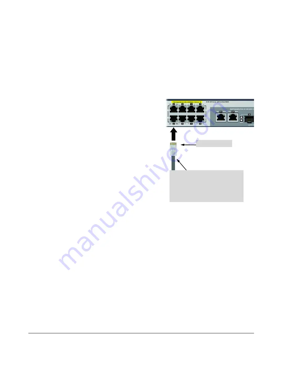
Using the RJ-45 Connectors
To connect:
Push the RJ-45 plug into the RJ-45
port until the tab on the plug clicks
into place. When power is on for the
switch and for the connected device,
the Link LED for the port should
light to confirm a powered-on device
(for example, an end node) is at the
other end of the cable.
If the Link LED does
not
go on when
the network cable is connected to
the port, see
“Diagnosing with the
LEDs”
in chapter 4,
“Troubleshooting”.
To disconnect:
Press the small tab on the plug and
pull the plug out of the port
.
RJ-45 connector
Unshielded twisted-pair cable:
• Category 3, 4, or 5 for 10 Mbps ports
• Category 5 or better for 100 Mbps ports
• Category 5e or better for 1000 Mbps ports
Maximum distance: 100 meters
Figure 2-13. Connecting network cables
Summary of Contents for ProCurve 2520-PoE
Page 1: ...HP ProCurve 2520G PoE Switches Installation and Getting Started Guide Power over Ethernet ...
Page 2: ......
Page 3: ...HP ProCurve 2520G PoE Switches Installation and Getting Started Guide ...
Page 20: ......
Page 46: ......
Page 52: ......
Page 66: ......
Page 85: ...B 7 Safety and EMC Regulatory Statements Safety Information China Safety Information China ...
Page 87: ...B 9 Safety and EMC Regulatory Statements EMC Regulatory Statements Korea Taiwan ...
Page 88: ...B 10 Safety and EMC Regulatory Statements EMC Regulatory Statements European Community ...
Page 89: ...B 11 Safety and EMC Regulatory Statements EMC Regulatory Statements ...
Page 90: ......
Page 100: ......


