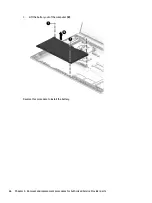


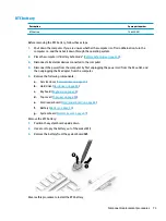
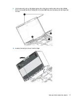
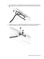


15.
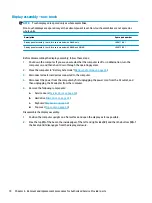
If it is necessary to remove or replace an IR display/camera cable, remove the cable from under the tab
that secures it to the enclosure (1), and then remove the cable from the display enclosure (2).
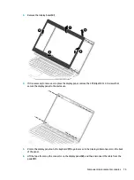
16.
If it is necessary to remove or replace an HD display/camera cable, remove the cable from under the tab
that secures it to the enclosure (1), and then remove the cable from the display enclosure (2).
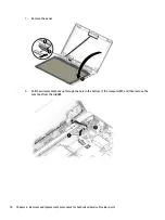
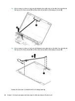
Reverse this procedure to reassemble the touch display assembly.
80
Chapter 6 Removal and replacement procedures for Authorized Service Provider parts
Summary of Contents for ProBook 450 G5
Page 1: ...HP ProBook 450 G5 Notebook PC Maintenance and Service Guide ...
Page 4: ...iv Important Notice about Customer Self Repair Parts ...
Page 6: ...vi Safety warning notice ...
Page 10: ...x ...
Page 32: ...Display components 22 Chapter 3 Illustrated parts catalog ...
Page 118: ...WWAN module removal 41 spare part numbers 41 108 Index ...


