background image

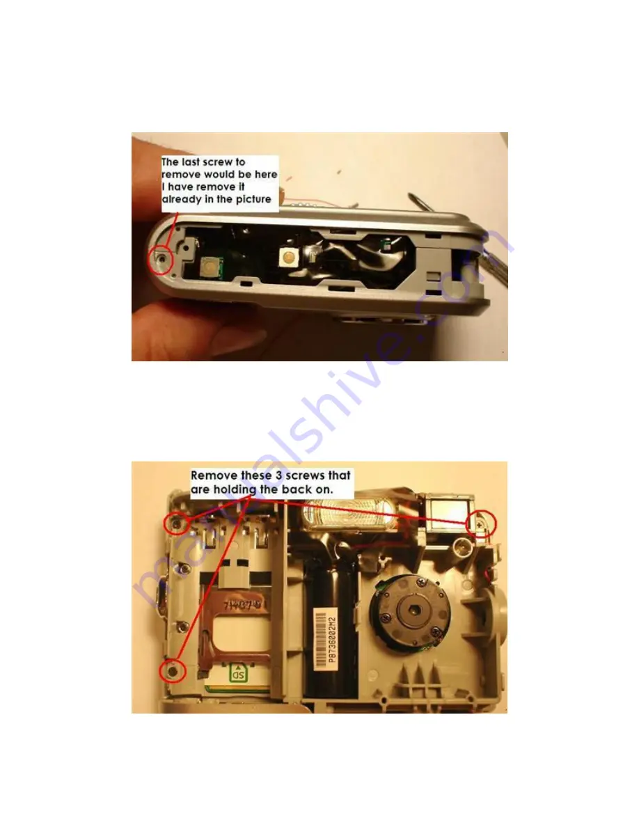
You will now see there are 3 more screws you have to remove, 2 on the side, 
where the Power/Shutter plate covered them, and one on the top of the camera.  
I have already removed the one on top, but it was in the corner where I circled. 


After removing these next 3 screws, you can finally take the front section off of 
the camera. Start this from the side where we just removed two of the screws. 
The other side clips in place, and it can be stubborn, but gentle twisting as you 
open it will help it come off there. 


Summary of Contents for Photosmart E337

Page 1: ...ors etc before touching any components inside the camera You should AT LEAST cover the camera lens and take a flash picture and then IMEDIATELY open the battery cover to prevent the flash from recharging Even so there will still be some charge leftover that might shock you or destroy the camera if shorted somewhere Before beginning this hack you need to remove the batteries and memory card from th...

Page 2: ...e out with a fingernail then use a small screwdriver to pry it out of a snap lock of sorts holding it on about halfway up the left side Now you slide the Power Shutter plate off Note that there is a catch on the top middle section slide the plate out to the right as shown and it will pop off ...

Page 3: ...I have already removed the one on top but it was in the corner where I circled After removing these next 3 screws you can finally take the front section off of the camera Start this from the side where we just removed two of the screws The other side clips in place and it can be stubborn but gentle twisting as you open it will help it come off there ...

Page 4: ...ress the menu button while turning the camera on So we want to solder a control wire to the Menu button This wire will later be twisted to and connected to the power wire on the opposite side of the servo connector or at the controller boards Power connection By adding this menu wire and connecting the power and Menu wires outside the camera the camera will still work normally outside the trail ca...

Page 5: ... right back edge of this board and solder the power and shutter control wires as shown When routing the wires out take care so that they won t interfere with any of the buttons and switches on the board Then reverse our steps and reassemble the camera ...

Page 6: ...installed it On the controller board side we will join the RED power and menu wires so that when connected to the controller the camera will always turn on in ACTION Mode and keep the ISO 400 setting Here the black wire is common ground and yellow connects the shutter ...

Page 7: ... the menu button You will see SHOOTING MODE in this you will choose ACTION This is ISO of 400 and helps greatly with our night pictures Then use the return button to get it back in Picture mode You will see a Runners icon in the bottom left hand corner of the screen Now power the camera off and Plug in the servo connector When the sensor turns the camera on it will always come on in the Action mod...

Reviews: