background image

34

Upgrading and Servicing Guide

6

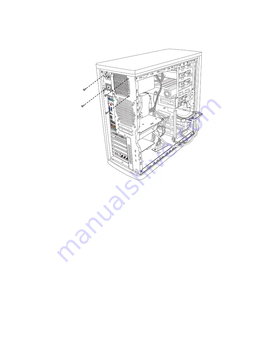
Remove the four screws holding the power supply to the back panel of the computer.

7

Pull out the power supply carefully:

a

Move it to the right (toward the front of the chassis) until it clears its left-most 
brackets.

b

Move it up to clear the bottom brackets.

c

Angle the power supply by rotating the right side down as far as you can.

d

Move the whole component to the right.

e

Lift the power supply out of the chassis.

Summary of Contents for Pavilion Elite d5100

Page 1: ...Upgrading and Servicing Guide ...

Page 2: ...proprietary information that is protected by copyright No part of this document may be photocopied reproduced or translated to another language without the prior written consent of HP Hewlett Packard Company P O Box 4010 Cupertino CA 95015 4010 USA Copyright 2008 Hewlett Packard Development Company L P May be licensed in the United States by one or both of U S Patents Nos 4 930 158 and 4 930 160 u...

Page 3: ...ng or Replacing an Optical Disc Drive 9 Removing an Optical Disc Drive 9 Removing the Front Bezel 11 Replacing or Adding an Optical Disc Drive 12 Replacing the Front Bezel 15 Adding or Replacing a Hard Disk Drive 16 Before You Begin 16 Removing a Hard Disk Drive 17 Adding or Replacing a Hard Disk Drive 19 Removing and Replacing Memory 20 Before You Begin 20 Removing a Memory Module 21 Replacing a ...

Page 4: ...iv Upgrading and Servicing Guide Removing and Replacing the Battery 30 Before You Begin 30 Removing and Replacing the Power Supply 32 Replacing the Power Supply 35 ...

Page 5: ...rvicing Guide Why Read This The Upgrading and Servicing Guide provides instructions on how to remove and replace the following hardware components in your computer Optical disc drives Hard disk drives Memory modules Add in cards Battery Power supply ...

Page 6: ...g side tabs Do not force it If the tabs break the cable cannot be replaced securely The illustration here shows two kinds of release tabs there are other types All connectors are keyed to fit in one orientation If it connects you can be confident it is the right connection WARNING Please read Additional Safety Information in your Limited Warranty and Support Guide before installing and connecting ...

Page 7: ...s screws within the chassis require a Phillips or a flathead screwdriver Hewlett Packard recommends using a magnetic tipped screwdriver A flathead screwdriver can be used with the screw seen here Components Front View The following shows locations of parts from the front with the doors open These are available bays and components not all drive bays are populated necessarily Component A Optical dis...

Page 8: ...n antistatic wrist strap and a conductive foam pad when working on system electronic components Have a Phillips and flathead screwdriver on hand magnetic tipped head is optimal Preparing the Computer To avoid injury and equipment damage always follow this procedure before opening the computer 1 Remove any of the following Memory card from the memory card reader Optical disc CD or DVD from the opti...

Page 9: ...Use a screwdriver to remove the two shipping screws A on the back cover These screws are for shipping only 3 Pull the handle B on the side panel and slide the side cover toward the rear until if falls open Set the cover aside The cover slides only about 2 5 centimeters 1 inch WARNING To reduce the risk of personal injury from electrical shock or hot surfaces disconnect the power cord from the elec...

Page 10: ...dia drive bay Adding or Replacing an Optical Disc Drive on page 9 C 3 1 2 inch drive bays Adding or Replacing an Optical Disc Drive on page 9 D Hard disk drive bays Adding or Replacing a Hard Disk Drive on page 16 E Memory RAM Removing and Replacing Memory on page 20 F Motherboard battery Removing and Replacing the Battery on page 30 G H Add in cards Adding or Replacing an Add in or a Graphics Car...

Page 11: ...ut 2 5 centimeters 1 inch toward the front of the computer 1 Holding the side panel place the lower edge of the panel onto the computer frame at an angle as shown Tabs on the lower part of the side panel fit into grooves on the frame and lock into place as the door slides forward and shut 2 With the panel tabs aligned in the computer slots move the rest of the panel toward the computer frame until...

Page 12: ...n this order after closing the computer 1 Reconnect the modem telephone cable and all other attached cables such as the keyboard mouse Ethernet and monitor cables 2 Reconnect external devices such as a printer 3 Reconnect the power cord 4 Turn on the computer and all peripherals such as the monitor WARNING To reduce the risk of electrical shock fire or damage to the equipment do not plug telecommu...

Page 13: ...ical drive See Locating Components Inside the Computer on page 6 Removing an Optical Disc Drive 1 Prepare the computer and remove the side cover Complete the Opening the Computer on page 4 2 From the side of the computer slide the green plastic drive lock toward the front of the computer to unlock the drive lock and unlock positions are marked WARNING Avoid touching sharp edges inside the computer...

Page 14: ...ent The cables should disconnect easily 2 4 From the inside of the computer push the drive toward the front of the computer CAUTION Never force a connector Do not push or pull too hard Many connectors have release tabs that must be pressed before disconnecting CAUTION Pull the connector by the handle cable housing only ...

Page 15: ...ront Bezel This procedure is required only when you are adding an optical disc drive or a 3 1 2 inch floppy or pocket media drive Otherwise the front bezel can be left intact 1 First remove the side cover See Removing the Side Computer Cover on page 5 2 From the inside of the chassis release the three tabs 2 forward through the slots 1 ...

Page 16: ... a Complete the procedure Removing the Front Bezel on page 11 b Remove the blank plate from the front bezel by holding it so the back side of the bezel is toward you Then squeeze the two tabs on either side of the plate you want to remove and push the plate forward away from you until it snaps out of the bezel c Remove the metal shield from the chassis bay by prying it out of the chassis If necess...

Page 17: ...ould look similar 4 From the front of the chassis gently push the optical disc drive into one of the three top bays on the front of the chassis until it is flush with the other bay fronts NOTE The top optical bay holds an optical drive with a maximum depth of 17 15 centimeters 6 3 4 inches The other two bays do not have this limitation ...

Page 18: ... the plastic drive lock toward the back of the computer until it is firmly locked and the optical drive cannot be pushed forward The lock travels over two raised bumps on the chassis and all the way back It does not go into position properly if the drive is not aligned 7 Connect the power and data cables gently but firmly into the back of the optical drive Some drive models may have a sound cable ...

Page 19: ...ver as described in Replacing the Computer Cover on page 7 Replacing the Front Bezel 1 Align the hooks on the right side of the front panel with the slots on the right side of the chassis front and press the right side of the front panel into place 2 Swing the front panel closed and then press the left side of the front panel to latch it into place ...

Page 20: ...er removable parts It is extremely sensitive to shock impact Do not bang or drop it Do not touch the circuit board Static electricity can damage the drive Be gentle and attentive Before You Begin Observe the following requirements before removing and replacing a hard drive CAUTION Before you remove the hard disk drive back up your personal files on the hard disk drive to an external storage device...

Page 21: ...r on page 4 2 Carefully disconnect the power and data cables Press down on the latch A on the top of the data cable before you disconnect it 3 Using your thumb squeeze the tab on the green hard drive carrier 1 and pull the hard drive out of the bay 2 CAUTION Pull the connectors straight out so as not to bend or damage the pins or connector A ...

Page 22: ...Pop the hard drive from its flexible carrier by twisting one of the carrier ends outward circled until it peels away from the drive CAUTION Handle hard disk drives with care Dropping or banging the hard disk drive can result in data loss ...

Page 23: ...ard drive is in its carrier align the carrier with the correct bay Slide the carrier all the way back until it is seated and clicks into place 4 Ensuring the cables are aiming straight into the connections so as not to bend or damage pins reconnect the power and data cables The cables click into place Never force the connection they should connect easily 5 Complete the procedures to replace the co...

Page 24: ...ecific memory module information and specifications 1 Go to http www hp com support in your Web browser 2 Select your country region and language 3 From the Support and Drivers page click See support and troubleshooting information enter the model number of your computer and then click Search CAUTION Using the wrong type of memory module could damage the system CAUTION Handle the memory module by ...

Page 25: ...g the Computer on page 4 2 Remove the optical disc drive See Removing an Optical Disc Drive on page 9 3 Locate the memory socket on the motherboard 4 Without disconnecting any cables move any cabling out of the way if necessary CAUTION Do not pull the memory module out of the socket Use the retaining clips to eject the module ...

Page 26: ...y module in antistatic packaging Replacing a Memory Module Upgrade the memory in your computer with memory of the same type and speed as the memory originally installed in your computer 1 Complete the procedure Replacing a Memory Module on page 22 2 Open both latches of the memory module socket CAUTION Handle the memory module by its edges only Be careful to not touch any memory module contacts To...

Page 27: ...Match the notch A on the memory module with the tab B on the memory socket Push the module carefully and firmly into the slot ensuring that the latches on both ends snap into place 5 Repeat steps 1 to 4 for the second memory slot as required 6 Replace any cabling that was moved 7 Complete the procedures to replace the computer side cover See Replacing the Computer Cover on page 7 ...

Page 28: ... an Add in or a Graphics Card Your computer contains several graphics or add in card slots that can be used to add components to your computer such as a TV tuner select models only You can also replace these cards with new cards Graphics card Modem card ...

Page 29: ...l cables attached to the card and then disconnect them You may have to pull out the card first to get access to the cables and then disconnect them In this case follow the next steps to pull out the card 4 Remove the screw or screws that hold the card to the frame 1 CAUTION Familiarize yourself with how the cables disconnect Some cables have metal tabs that have to be pressed to unlock the cable O...

Page 30: ...s a graphics card unlock it by releasing the latch connecting the card to the motherboard The latch may be hidden behind the card The following illustration shows an example tab WARNING Take care with sharp edges around the graphics card slots ...

Page 31: ...tab down grasp the card at the top and carefully pull it straight out of the slot CAUTION Handle the graphics card by its edges only Be careful to not touch any memory module contacts Touching the gold contacts may damage the module Avoid touching the memory chips ...

Page 32: ...in cards is the same as for the graphics card but there is no release tab 1 Remove the screw or screws that hold the card to the frame 2 Make a note of any internal cables attached to the card and then disconnect them 3 Hold the top of the card and carefully pull it straight out of the card slot ...

Page 33: ...cing a Graphics or Add in Card When adding a card you first have to force out the blank PCI faceplate Be careful not to bend the EMI shields The following figure shows a bent shield CAUTION A bent EMI shield could cause an electrical short ...

Page 34: ...s timekeeping capability When the battery starts to weaken the date and time may be incorrect If the battery fails replace it with a CR2032 lithium battery 3 volt 220 mAh rating or its equivalent Before You Begin Observe the following requirements before removing and replacing the battery A B WARNING There is danger of explosion if the battery is incorrectly replaced Replace only with the same or ...

Page 35: ... side on a soft protective surface 3 If an add in or graphics card is in the way of the battery remove the graphics card first See Removing a Graphics Card on page 25 4 Remove any cabling if necessary to reach the battery 5 Move the retaining tab 1 away from the battery Lift the battery from the socket 6 Install the new CR2032 battery in the socket with the positive side facing up ...

Page 36: ...r Supply Your computer comes with a 460W or 700W power supply You can replace the power supply with an equivalent one 1 Prepare the computer and remove the computer cover Complete the procedure Opening the Computer on page 4 2 Make note of all cables plugged into the power supply and where they are connected within the chassis to ensure everything will be reconnected 3 Methodically release the cab...

Page 37: ...ower supply remove the additional shipping screw as shown in the figure NOTE Do not cut cable rings The cables are routed in reusable cable rings which can be opened to remove the cables and closed to secure the cables in their routing path placeholder illustration of screw placement inside the chassis for the 700W power supply ...

Page 38: ... out the power supply carefully a Move it to the right toward the front of the chassis until it clears its left most brackets b Move it up to clear the bottom brackets c Angle the power supply by rotating the right side down as far as you can d Move the whole component to the right e Lift the power supply out of the chassis ...

Page 39: ...ment it was originally 2 Reinsert the four screws that hold the power supply in place 3 Reconnect each cable to its component It can be difficult to see where some cables reconnect if other components or cables are in the way Do not force connections WARNING Be careful of sharp edges inside the chassis It can be difficult to see where some cables reconnect if other components or cables are in the ...

Page 40: ...Printed in ...

Reviews: