


685
Managing data links
This section provides information about data link management and configuration.
Overview
Introduction to E1 and T1
Plesiochronous digital hierarchy (PDH) includes two major communications systems: ITU-T E1 system and
ANSI T1 system. The E1 system is dominant in European and some non-Europe countries. The T1 system
is dominant in USA, Canada and Japan.
E1 and T1 use the same sampling frequency (8 kHz), PCM frame length (125
μ
s), bits per code (8 bits)
and timeslot bit rate (64 kbps). They differ in these aspects:
•
E1 adopts A law coding/decoding of 13-segment but T1 adopts
μ
law coding/decoding of
15-segment.
•
Each PCM primary frame of E1 contains 32 timeslots but that of T1 contains 24 timeslots. Each
PCM primary frame of E1 contains 256 bits but that of T1 contains 193 bits. Therefore, E1 provides
2.048 Mbps bandwidth and T1 provides 1.544 Mbps bandwidth.
E1 and T1 voice functions
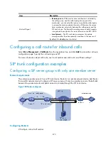
E1 and T1 mainly provide voice and signaling trunks to the PSTN. To realize this function, the router must
have E1 and T1 voice interfaces and be configured with functions required for transmitting voice over E1
and T1 lines.
The E1 and T1 voice physical interfaces are VE1 and VT1 interfaces, respectively.
PSTN and routers are connected through E1/T1 trunks, as shown in
.
Figure 716
Network diagram
E1/T1 voice transmission allows a router to provide more channels of voice communication, greatly
improving router use and broadening service range.
Summary of Contents for MSR SERIES
Page 17: ...xv Documents 835 Websites 835 Conventions 836 Index 838 ...
Page 20: ...3 Figure 3 Initial page of the Web interface ...
Page 42: ...25 Figure 13 Firefox Web browser setting ...
Page 59: ...42 Figure 27 Checking the basic service configuration ...
Page 73: ...56 Figure 35 Sample interface statistics ...
Page 156: ...139 Figure 139 Rebooting the 3G modem ...
Page 168: ...151 Figure 152 Configuring Web server 2 ...
Page 174: ...157 Figure 158 Configure the URL filtering function ...
Page 242: ...225 Figure 233 Enabling the DHCP client on interface Ethernet 0 1 ...
Page 247: ...230 Figure 236 The page for configuring an advanced IPv4 ACL ...
Page 255: ...238 Figure 241 Advanced limit setting ...
Page 298: ...281 e Click Apply 2 Configure Router B in the same way Router A is configured ...
Page 400: ...383 Figure 387 Verifying the configuration ...
Page 405: ...388 ...
Page 523: ...506 Figure 530 Ping configuration page ...
Page 775: ...758 Figure 785 Configuring a jump node ...


