


570
Verifying the configuration
Place a call from Telephone A to Telephone B. Router B forwards the call to Telephone C when Telephone
B is busy. Finally, Telephone A and Telephone C start a conversation
Configuring call transfer
Network requirements
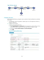
As shown in
, call transfer enables Telephone A to transfer Telephone B to Telephone C. After
the call transfer is completed, Telephone B and Telephone C are in a conversation.
The whole process is as follows:
1.
Call Telephone B from Telephone A, and then Telephone B and Telephone A are in a conversation.
2.
Perform a hookflash at Telephone A to put the call with Telephone B on hold.
3.
Call Telephone C (3000) from Telephone A after hearing dial tones.
4.
Hang up Telephone A.
5.
Telephone B and Telephone C are in a conversation and call transfer is completed.
Figure 591
Network diagram
Configuration procedure
Before performing the following configuration, make sure that Router A, Router B and Router C are
reachable to each other.
1.
Complete basic voice call configurations: complete basic voice call configurations on Router A,
Router B, and Router C.
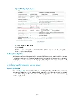
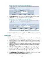
2.
Configure call transfer:
# Configure call hold and call transfer on Router A.
a.
Select
Voice Management
>
Local Number
from the navigation tree, click the icon of local
number 1000 in the local number list to access the call services configuration page.
b.
Select
Enable
for
Call Hold
.
c.
Select
Enable
for
Call Transfer
.
d.
Click
Apply
.
1000
Eth1/1
10.1.1.1/24
3000
Router A
Eth1/1
20.1.1.2/24
2000
Eth1/2
10.1.1.2/24
Eth1/1
20.1.1.1/24
Router B
Router C
Telephone B
Telephone C
Telephone A
Summary of Contents for MSR SERIES
Page 17: ...xv Documents 835 Websites 835 Conventions 836 Index 838 ...
Page 20: ...3 Figure 3 Initial page of the Web interface ...
Page 42: ...25 Figure 13 Firefox Web browser setting ...
Page 59: ...42 Figure 27 Checking the basic service configuration ...
Page 73: ...56 Figure 35 Sample interface statistics ...
Page 156: ...139 Figure 139 Rebooting the 3G modem ...
Page 168: ...151 Figure 152 Configuring Web server 2 ...
Page 174: ...157 Figure 158 Configure the URL filtering function ...
Page 242: ...225 Figure 233 Enabling the DHCP client on interface Ethernet 0 1 ...
Page 247: ...230 Figure 236 The page for configuring an advanced IPv4 ACL ...
Page 255: ...238 Figure 241 Advanced limit setting ...
Page 298: ...281 e Click Apply 2 Configure Router B in the same way Router A is configured ...
Page 400: ...383 Figure 387 Verifying the configuration ...
Page 405: ...388 ...
Page 523: ...506 Figure 530 Ping configuration page ...
Page 775: ...758 Figure 785 Configuring a jump node ...