


508
1.
Select
WiNet
from the navigation tree.
When WiNet is disabled, a dialog box
Only the WiNet administrator supports the function
appears.
2.
Click
OK
to enter the
Setup
3.
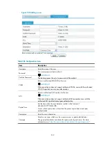
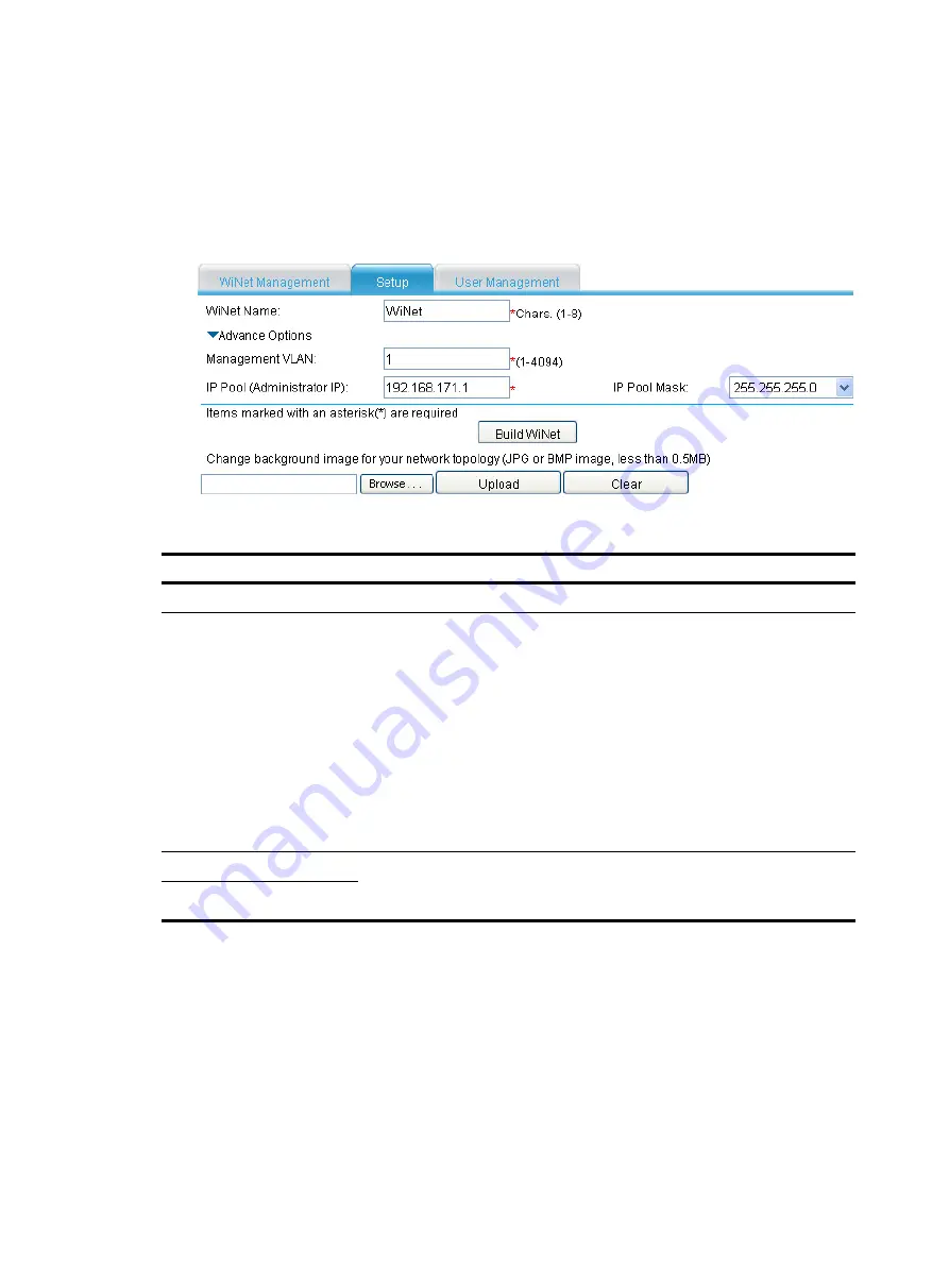
Configure WiNet, as shown in
Figure 532
WiNet setup page
Table 205
Configuration items
Item Description
WiNet Name
Enter a WiNet name.
Management VLAN
Enter a management VLAN ID in the WiNet. You can enter an existing static
VLAN only.
The management VLAN is used by WiNet packets for communication. It
actually defines the WiNet management range and delivers the following
functions:
•
Isolates WiNet management packets from other packets.
•
Enables internal communication between the administrator, members, and
candidates.
WiNet management requires that the management VLAN traffic be permitted
on the administrator’s ports (including cascade ports if there is any) connected
to members, candidates, and the external network.
IP Pool (Administrator IP)
Enter an IP address and select a network mask for the administrator. After that,
each WiNet member is assigned an IP address on the same subnet as the
administrator.
Mask of IP Pool
After a WiNet is built, you cannot configure items on the
Setup
page, and the
Build WiNet
button
changes to
Close WiNet
. To delete the WiNet, click the
Close WiNet
button.
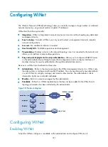
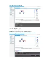
Setting the background image for the WiNet topology diagram
The WiNet topology diagram is displayed in the
WiNet Management
page and uses a white
background by default. You can customize the background image by uploading a JPG or BMP image
(which is less than 0.5 MB).
Select
WiNet
from the navigation tree and then click the
Setup
tab to enter the configuration page as
shown in
Summary of Contents for MSR SERIES
Page 17: ...xv Documents 835 Websites 835 Conventions 836 Index 838 ...
Page 20: ...3 Figure 3 Initial page of the Web interface ...
Page 42: ...25 Figure 13 Firefox Web browser setting ...
Page 59: ...42 Figure 27 Checking the basic service configuration ...
Page 73: ...56 Figure 35 Sample interface statistics ...
Page 156: ...139 Figure 139 Rebooting the 3G modem ...
Page 168: ...151 Figure 152 Configuring Web server 2 ...
Page 174: ...157 Figure 158 Configure the URL filtering function ...
Page 242: ...225 Figure 233 Enabling the DHCP client on interface Ethernet 0 1 ...
Page 247: ...230 Figure 236 The page for configuring an advanced IPv4 ACL ...
Page 255: ...238 Figure 241 Advanced limit setting ...
Page 298: ...281 e Click Apply 2 Configure Router B in the same way Router A is configured ...
Page 400: ...383 Figure 387 Verifying the configuration ...
Page 405: ...388 ...
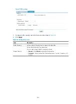
Page 523: ...506 Figure 530 Ping configuration page ...
Page 775: ...758 Figure 785 Configuring a jump node ...