


375
Configuring GRE
You can configure GRE over IPv4 tunnels through the Web interface.
Overview
Generic Routing Encapsulation (GRE) is a protocol designed for encapsulating and carrying the packets
of one network layer protocol (for example, IP or IPX) over another network layer protocol (for example,
IP). GRE is a tunneling technology and serves as a Layer 3 tunneling protocol.
A GRE tunnel is a virtual point-to-point connection for transferring encapsulated packets. Packets are
encapsulated at one end of the tunnel and de-encapsulated at the other end.
depicts the
encapsulation and de-encapsulation processes.
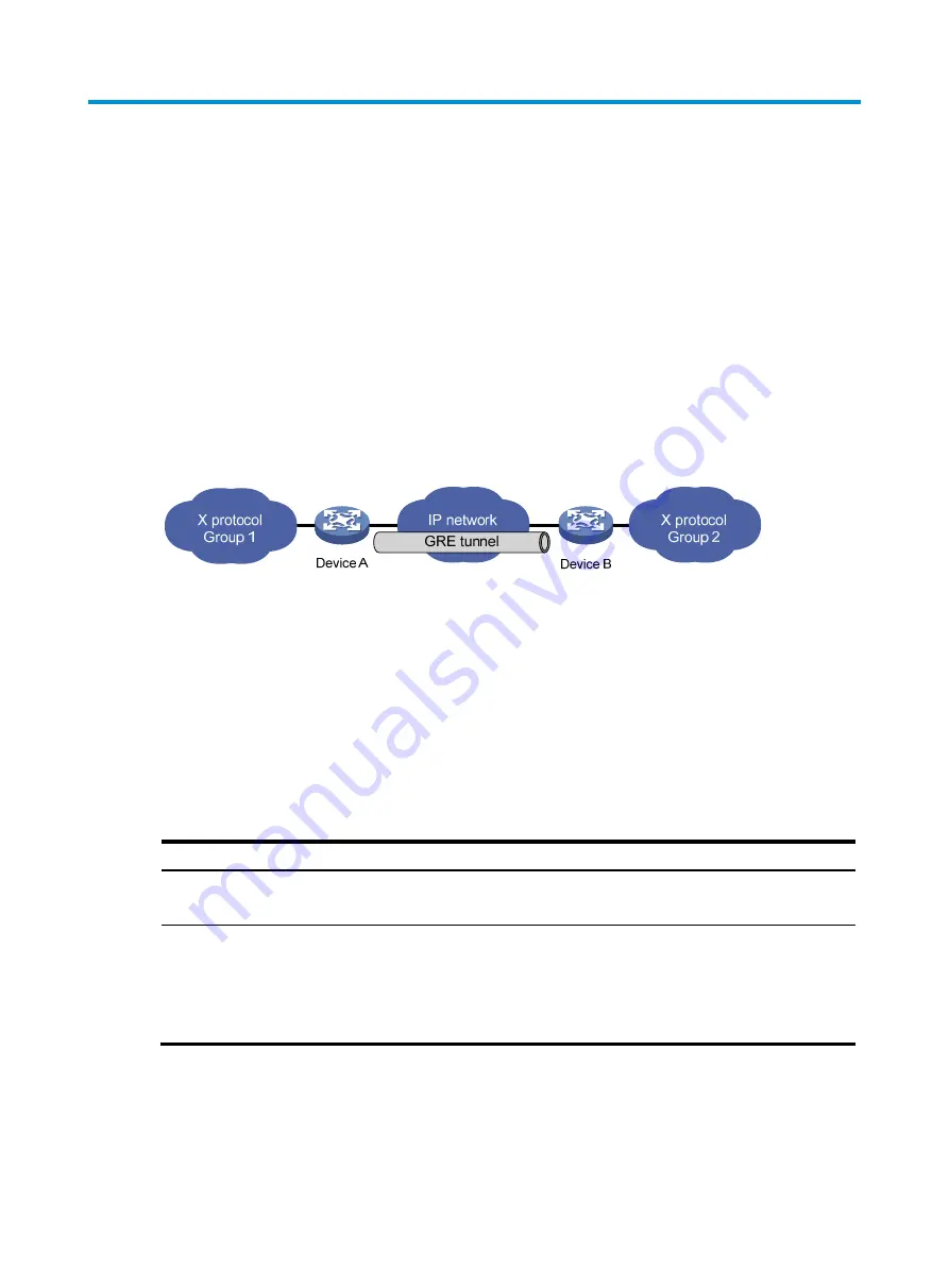
Figure 375
X protocol networks interconnected through the GRE tunnel
For more information about GRE, see
Layer 3—IP Services Configuration Guide
in
HP MSR Router Series
Configuration Guides (V5)
.
Configuring a GRE over IPv4 tunnel
Before you configure a GRE over IPv4 tunnel, configure an IP address for the interface (such as a VLAN
interface, an Ethernet interface, or a Loopback interface) to be used as the source interface of the tunnel
interface.
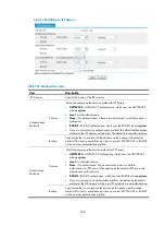
Recommended configuration procedure
Task Remarks
1.
Required.
Create a tunnel interface and configure GRE tunnel related parameters.
2.
Configure a route through
the tunnel.
Optional.
Each end of the tunnel must have a route (static or dynamic) through the
tunnel to the other end, so that GRE encapsulated packets can be forwarded
correctly.
For more information about route configuration, see "Configuring routes."
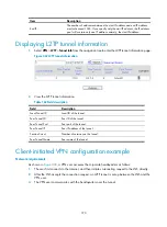
Creating a GRE tunnel
1.
Select
VPN
>
GRE
from the navigation tree to enter the GRE tunnel configuration page, as shown
Summary of Contents for MSR SERIES
Page 17: ...xv Documents 835 Websites 835 Conventions 836 Index 838 ...
Page 20: ...3 Figure 3 Initial page of the Web interface ...
Page 42: ...25 Figure 13 Firefox Web browser setting ...
Page 59: ...42 Figure 27 Checking the basic service configuration ...
Page 73: ...56 Figure 35 Sample interface statistics ...
Page 156: ...139 Figure 139 Rebooting the 3G modem ...
Page 168: ...151 Figure 152 Configuring Web server 2 ...
Page 174: ...157 Figure 158 Configure the URL filtering function ...
Page 242: ...225 Figure 233 Enabling the DHCP client on interface Ethernet 0 1 ...
Page 247: ...230 Figure 236 The page for configuring an advanced IPv4 ACL ...
Page 255: ...238 Figure 241 Advanced limit setting ...
Page 298: ...281 e Click Apply 2 Configure Router B in the same way Router A is configured ...
Page 400: ...383 Figure 387 Verifying the configuration ...
Page 405: ...388 ...
Page 523: ...506 Figure 530 Ping configuration page ...
Page 775: ...758 Figure 785 Configuring a jump node ...