


104
HoldTime: 150
Uptime: 00:00:32
Expires: 00:01:58
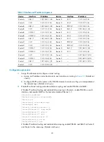
BIDIR-PIM configuration example
Network requirements
In the BIDIR-PIM domain shown in
, Source 1 and Source 2 send different multicast information
to multicast group 225.1.1.1. Host A and Host B receive multicast information from the two sources.
Serial 2/1 of Router C acts as a C-BSR, and loopback interface 0 of Switch C acts as a C-RP of the
BIDIR-PIM domain.
IGMPv2 runs between Router B and Host A and between Router D and Host B.
Figure 34
Network diagram
shows the interface and IP address assignment, and network topology scheme.
Table 11
Interface and IP address assignment
Device Interface
IP address
Router A
Ethernet 1/1
192.168.1.1/24
Router A
Serial 2/1
10.110.1.1/24
Router B
Ethernet 1/1
192.168.2.1/24
Router B
Serial 2/1
10.110.1.2/24
Router B
Serial 2/2
10.110.2.1/24
Router C
Serial 2/1
10.110.2.2/24
Router C
Serial 2/2
10.110.3.1/24
Router C
Loopback 0
1.1.1.1/32
Router D
Ethernet 1/1
192.168.3.1/24
Router D
Ethernet 1/2
192.168.4.1/24
BIDIR-PIM
Source 1
Source 2
Host A
Receiver 1
Router A
S2/1
S2/1
S2/2
S2/1
S2/2
S2/1
Eth1/1
Eth1/1
Et
h1/1
Eth1/2
Router D
Router C
Router B
Host B
Receiver 2
Loop0