background image

Connecting the Monitor Power

1.

Place the monitor in a convenient, well-ventilated location near the computer.

2.

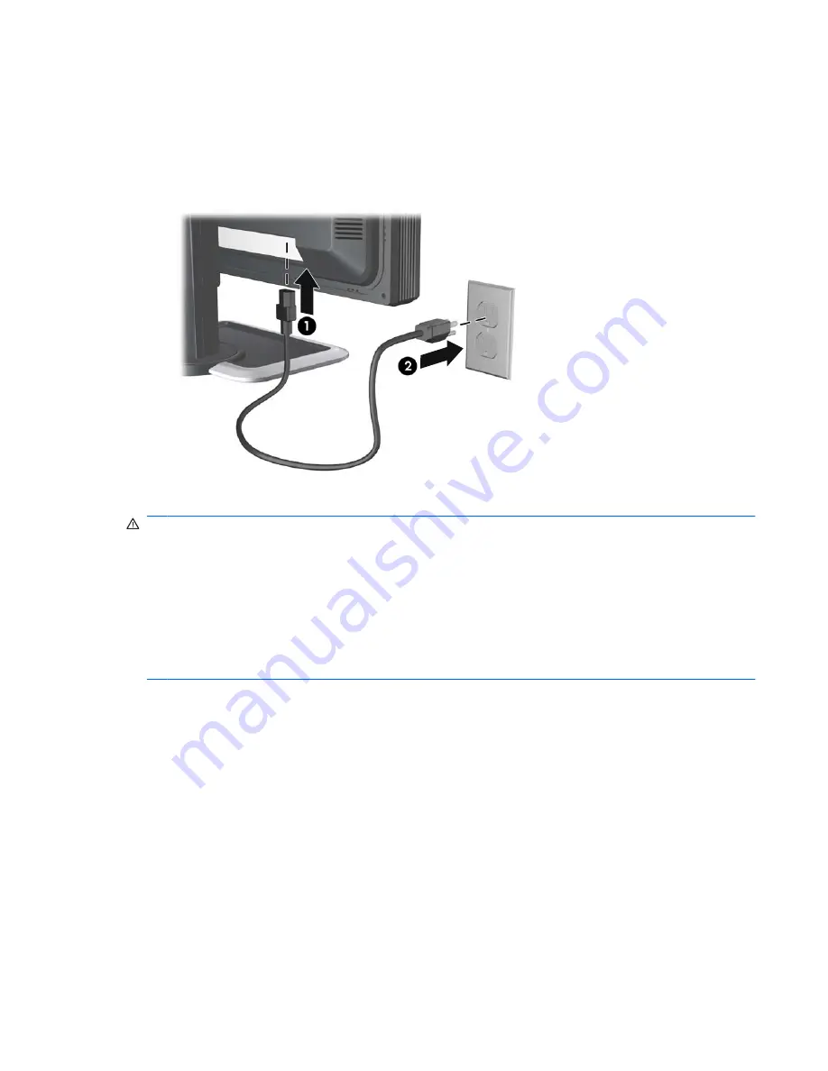
Connect one end of the power cable to the AC power connector on the back of the monitor (1),
and the other end to an electrical wall outlet (2).

Figure 3-4

  Connecting the Power Cable

WARNING!

To reduce the risk of electric shock or damage to the equipment:

• Do not disable the power cord grounding plug. The grounding plug is an important safety feature.

• Plug the power cord into a grounded (earthed) electrical outlet that is easily accessible at all times.

• Disconnect power from the equipment by unplugging the power cord from the electrical outlet.

For your safety, do not place anything on power cords or cables. Arrange them so that no one may
accidentally step on or trip over them. Do not pull on a cord or cable. When unplugging from the electrical
outlet, grasp the cord by the plug.

Connecting the Monitor Power

11

Summary of Contents for LP2480zx - DreamColor - 24" LCD Monitor

Page 1: ...HP LP2480zx LCD Monitor User Guide ...

Page 2: ...e information in this document is provided as is without warranty of any kind including but not limited to the implied warranties of merchantability and fitness for a particular purpose and is subject to change without notice The warranties for Hewlett Packard products are set forth in the express limited warranty statements accompanying such products Nothing herein should be construed as constitu...

Page 3: ...specifications WARNING Text set off in this manner indicates that failure to follow directions could result in bodily harm or loss of life CAUTION Text set off in this manner indicates that failure to follow directions could result in damage to equipment or loss of information NOTE Text set off in this manner provides important supplemental information iii ...

Page 4: ...iv About This Guide ...

Page 5: ...12 Turning on the Monitor 14 Using the Accessory Rails 15 Removing the Monitor Pedestal Base 15 Mounting the Monitor 16 Locating the Rating Labels 18 4 Operating the Monitor Software and Utilities 19 The Information File 19 The Image Color Matching File 19 Installing the INF and ICM Files 20 Installing from the CD 20 Downloading from the Worldwide Web 20 Using the Auto Adjustment Function 21 Front...

Page 6: ...y Resolutions 46 Entering User Modes 47 Energy Saver Feature 47 Appendix D Agency Regulatory Notices Federal Communications Commission Notice 48 Modifications 48 Cables 48 Declaration of Conformity for Products Marked with the FCC Logo United States Only 48 Canadian Notice 49 Avis Canadien 49 European Union Regulatory Notice 49 German Ergonomics Notice 50 Japanese Notice 50 Korean Notice 50 Power ...

Page 7: ...stable white point of 4K to 12K using the LED backlight no loss of dynamic range to provide maximum flexibility Adjustable gamma of 1 0 to 3 0 with a step size of 0 1 to provide maximum flexibility Adjustable luminance of 50 to 250 cd m2 with a wide adjustment range for maximum flexibility in a working environment and ability to adjust down to very low luminance levels 50 cd m2 Very high color and...

Page 8: ...e monitor DisplayPort 1 1 and HDMI 1 3 inputs through the panel for support of 1 07 B colors HDCP copy protection support on DVI digital DisplayPort and HDMI inputs to enable the display of protected content Support for 2048 x 1200 and 2048 x 1080 modes using cropping to support commonly used resolutions used by animation studios Backlight bezel buttons and OSD button labels to help make working w...

Page 9: ...tion CD that includes HP Display Assistant software monitor driver software and product documentation Energy saver feature to meet requirements for reduced power consumption Compliant with the following regulated specifications European Union CE Directives Swedish MPR II 1990 Swedish TCO Requirements HP LP2480zx Model 3 ...

Page 10: ...from the electrical outlet grasp the cord by the plug To reduce the risk of serious injury read the Safety and Comfort Guide It describes proper workstation setup posture and health and work habits for computer users and provides important electrical and mechanical safety information This guide is located on the Web at http www hp com ergo and or on the documentation CD if one is included with the...

Page 11: ...rovider Use only a power source and connection appropriate for this monitor as indicated on the label back plate of the monitor Be sure the total ampere rating of the products connected to the outlet does not exceed the current rating of the electrical outlet and the total ampere rating of the products connected to the cord does not exceed the rating of the cord Look on the power label to determin...

Page 12: ...r screen with an antistatic screen cleaner CAUTION Do not use benzene thinner ammonia or any other volatile substances to clean the monitor or the screen These chemicals may damage the cabinet finish as well as the screen Shipping the Monitor Keep the original packing box in a storage area You may need it later if you move or ship the monitor 6 Chapter 2 Safety and Maintenance Guidelines ...

Page 13: ...d Installing the Monitor Pedestal Base NOTE Do not install the pedestal base if the monitor will be used on a wall swing arm or other mounting fixture instead see Mounting the Monitor on page 16 in this chapter 1 Using both hands position the monitor over the pedestal base CAUTION Do not touch the surface of the LCD panel Pressure on the panel may cause non uniformity of color or disorientation of...

Page 14: ...or 4 HDMI Connector Connects the HDMI signal cable to the monitor 5 DVI I Connectors Connects the DVI I to VGA signal cable or DVI I to DVI D signal cable to the monitor 6 Component Connectors Connects Component signal cables to the monitor 7 S Video Connector Connects an S Video signal cable to the monitor 8 Composite Connector Connects a Composite signal cable to the monitor 9 USB Upstream Conne...

Page 15: ...gnal cable provided Connect the DVI I to DVI D signal cable to the DVI I connector on the monitor and the other end to the DVI D connector on the computer For analog operation use the DVI I to VGA signal cable provided Connect the DVI I to VGA signal cable to a DVI I connector on the monitor and the other end to the VGA connector on the computer DisplayPort Connect the DisplayPort cable provided t...

Page 16: ...ately Composite Connect a Composite cable to the Composite connector on the monitor and the Composite connector on the input device for analog operation Cable purchased separately Cable Management Before connecting the cables route them through the opening on the neck of the monitor s pedestal Figure 3 3 Using the Cable Management Feature Table 3 2 Signal Connectors and Cables continued 10 Chapter...

Page 17: ...nt Do not disable the power cord grounding plug The grounding plug is an important safety feature Plug the power cord into a grounded earthed electrical outlet that is easily accessible at all times Disconnect power from the equipment by unplugging the power cord from the electrical outlet For your safety do not place anything on power cords or cables Arrange them so that no one may accidentally s...

Page 18: ...the USB connector on the rear panel of the computer and the other end to the upstream USB connector on the monitor 2 Connect the USB devices to the USB downstream connectors on the side panel of the monitor Figure 3 5 Connecting USB Devices Adjusting the Monitor 1 Tilt the monitor s panel forward or backward to set it to a comfortable eye level Figure 3 6 Tilting the Monitor 12 Chapter 3 Setting U...

Page 19: ... the column prevents the display panel from sliding up when the monitor is lifted If the display panel is locked in the lowest height position a Make sure that the monitor is safely positioned on a stable surface b Gently push down on the display panel c While pushing down the display panel press the lock down release button on the front of the column d Guide the display panel up to the desired he...

Page 20: ...n the monitor s front panel then select OSD Control OSD Rotation CAUTION Monitor display panel orientations of 180 and 270 degrees are not supported and may result in damage to the monitor Turning on the Monitor 1 Press the power switch to turn on the computer 2 Verify the master power switch on the rear of the monitor is in the on I position 3 Press the power button on the front of the monitor CA...

Page 21: ... to mount the panel on a wall a swing arm or other mounting fixture This monitor has a Quick Release mechanism that allows you to easily remove and replace the monitor panel to the pedestal base CAUTION Before beginning to disassemble the monitor be sure the monitor is turned off and the power and signal cables are both disconnected Also disconnect any USB cables that are connected to the monitor ...

Page 22: ...ution to the monitor four 4 mm 0 7 pitch and 10 mm long screws are required not provided with the monitor Longer screws must not be used because they may damage the monitor It is important to verify that the manufacturer s mounting solution is compliant with the VESA standard and is rated to support the weight of the monitor display panel For best performance it is important to use the power and v...

Page 23: ...Release CAUTION The Quick Release can also be installed directly to a wall to mount the monitor panel It is designed to support a maximum of up to 10 9 kg 24 lbs If you are mounting to a wall HP recommends that you consult with a qualified engineering architectural or construction professional to determine the appropriate type and quantity of mounting fasteners required for your application and to...

Page 24: ...serting the Monitor Panel into the Quick Release Locating the Rating Labels The rating labels on the monitor provide the spare part number product number and serial number You may need these numbers when contacting HP about the monitor model The rating labels are located on the rear of the monitor display panel Figure 3 15 Locating the Rating Labels 18 Chapter 3 Setting Up the Monitor ...

Page 25: ... monitor is Microsoft Windows Plug and Play compatible and the monitor will work correctly without installing the INF file Monitor Plug and Play compatibility requires that the computer s graphic card is VESA DDC2 compliant and that the monitor connects directly to the graphics card Plug and Play does not work through separate BNC type connectors or through distribution buffers boxes The Image Col...

Page 26: ...tion and refresh rates appear in the Windows Display control panel NOTE You may need to install the digitally signed monitor INF and ICM files manually from the CD in the event of an installation error Refer to the Monitor Driver Software Readme file on the CD Downloading from the Worldwide Web To download the latest version of INF and ICM files from the HP monitors support Web site 1 Refer to htt...

Page 27: ...er picture To use the auto adjustment feature 1 Allow the monitor to warm up for 20 minutes before adjusting 2 Press the minus button on the monitor front panel You can also press the Menu button then select Image Control Auto Adjustment from the OSD Main Menu Refer to Adjusting the Monitor Settings on page 23 in this chapter If the result is not satisfactory continue with the procedure 3 Insert t...

Page 28: ...Plus Navigates forward through the OSD menu and increases adjustment levels 4 Minus Navigates backward through the OSD menu and decreases adjustment levels When the OSD menu is inactive activates the auto adjustment feature to optimize the screen image 5 Menu Select Opens selects or exits the OSD menu 6 Power LED Green Fully powered Amber Sleep mode Flashing Amber Sleep Timer mode 7 Power Turns th...

Page 29: ...e monitor 2 To access the OSD Menu press the Menu button on the monitor s front panel 3 To navigate through the OSD Menu press the plus button on the monitor s front panel to scroll down or the minus button to scroll up 4 To select an item from the OSD Menu use the or buttons to scroll to and highlight your selection then press the Menu button to select that function 5 Adjust the item using the or...

Page 30: ...t for the sRGB standard Rec 709 Factory calibrated preset for the Rec 709 standard DCI P3 Emulation Factory calibrated emulation preset for the DCI P3 standard Note the monitor s color gamut does not fully enclose the DCI P3 color space User 7 User calibrated preset that must be set up before use Luminance Brightness Adjusts the Luminance Brightness level of the screen The control range is 50 250 ...

Page 31: ...und Adjusting the Clock will also change the horizontal screen image Clock Phase Adjusts the focus of the display This adjustment allows you to remove any horizontal noise and clear or sharpen the image of characters Black Level Adjusts the black level or offset of the monitor The factory default value is 128 no offset and the range is 0 to 255 OverDrive Disables or enables the overdrive feature T...

Page 32: ...sabled when DDC CI Support is disabled Bezel Button LED Disables or enables the bezel button backlight LEDs Auto EDID Update Disables or enables the monitor s automatic update of the DVI DisplayPort and HDMI extended display identification data EDID based on the selected Color Space preset The EDID will only be updated for the input selected for the primary window Sleep Timer Provides the timer ad...

Page 33: ...ed on the bottom of the main menu OSD Transparency Adjust to view the background information through the OSD OSD Timeout Sets the time duration in seconds that the OSD is visible after the last button is pressed The range is 10 60 seconds The factory default is 40 seconds OSD Rotation Rotates the OSD menus and messages to support the monitor s Pivot feature The choices are 0 and 90 degrees Video I...

Page 34: ...Clock Phase settings are dependent on the main Clock setting Use these controls only when the auto adjustment function does not provide a satisfactory image Clock Increases decreases the value to minimize any vertical bars or stripes visible on the screen background Clock Phase Increases decreases the value to minimize video distortion or video jitter NOTE When using the controls you will obtain t...

Page 35: ...OSD Lockout The OSD can be enabled or disabled by pressing and holding the Menu button on the front panel for 10 seconds If the OSD is locked the warning message OSD Lockout displays for ten seconds If the OSD is locked press and hold the Menu button for 10 seconds to unlock the OSD If the OSD is unlocked press and hold the Menu button for 10 seconds to lock the OSD Power Button Lockout Indicates ...

Page 36: ...play the OSD Menu 2 Scroll down and highlight Management 3 Press the Menu button to select Management 4 Scroll down and highlight and select Sleep Timer Set Current Time NOTE You must set the current local time before you reset the time for Sleep Time or On Time Note that the time is displayed in a 24 hour clock format For example 1 15 p m is displayed as 13 hours 15 minutes 5 Press the Menu butto...

Page 37: ...ng the HP X Rite color calibration kit The calibration kit is required to set up new color space presets and calibrate the monitor to maintain the color performance For more information on the color calibration kit refer to http www hp com For best color performance HP recommends the monitor be used in an environment with minimal ambient light If the monitor is used in a typical office environment...

Page 38: ...ut device gamuts such as Adobe RGB and sRGB Rec 709 this enables accurate emulation of these standards by means of gamut adaptation capabilities built into the monitor NOTE In the earlier 1931 CIE xy space the gamut area of the LP2480zx is 110 that of the 1953 NTSC gamut The monitor front end electronics provides support for the gamut adaptation mentioned above including numerous factory adjusted ...

Page 39: ...40 0 640 0 680 y 0 300 0 330 0 340 0 330 0 330 0 320 u 0 529 0 451 0 433 0 451 0 451 0 496 v 0 517 0 523 0 526 0 523 0 523 0 526 Green x 0 205 0 210 0 310 0 300 0 300 0 265 y 0 715 0 710 0 595 0 600 0 600 0 690 u 0 073 0 076 0 130 0 125 0 125 0 099 v 0 576 0 576 0 563 0 563 0 563 0 578 Blue x 0 150 0 150 0 155 0 150 0 150 0 150 y 0 045 0 060 0 070 0 060 0 060 0 060 u 0 185 0 175 0 176 0 175 0 175 ...

Page 40: ...However the display luminance brightness and white point may be adjusted using the on screen display OSD or HP Display Assistant software The following sections describe the theory behind this emulation the hardware provided to support it in the LP2480zx and information on its usage Theory of Operation In general most display devices such as CRT or LCD based monitors may be mathematically modeled ...

Page 41: ...gure A 3 Matrix Multiplication of Input Values In essence the R G and B values may be seen as gain controls on three light sources whose peak outputs are described as XR YR ZR XG YG ZG and XB YB ZB The display device itself in this case the LCD module used in the LP2480zx monitor of course has its own native characteristics which may be modeled as described above The problem of emulating a differe...

Page 42: ... the color remapping which is referred to as R is a combination of the matrix that transforms R G B to X Y Z values under the target standard AS and the inverse of the corresponding matrix for the existing display device AD In other words R AD 1 AS This stage must then be followed by a second look up table the post LUT which linearizes the existing display device specifically it contains the inver...

Page 43: ...Display Assistant software or the optional HP X Rite calibration software These provide the correct programming of the color management hardware described above as needed for the desired color space characteristics NOTE Refer to the monitor s DDC CI and USB communication specification for more details Summary of Color Space Selection Availability As noted the selection of output device color space...

Page 44: ...d the LCD module itself With most video sources which typically provide video information at the standard 8 bits color or 24 bits pixel and across all of the LP2480zx s various inputs the increased accuracy of the LP2480zx LCD module is used to provide more accurate color within the selected standard color space However 30 bit sources may also be directly supported using the DisplayPort 1 1 and HD...

Page 45: ...d CRT display fairly well and so was assumed for years to be the typical response curve of an electronic display device As it turns out encoding image information under the assumption of an output device response of this nature has other advantages and so it remains very common for standard output device specifications to require a transfer function or response curve which is of this general natur...

Page 46: ...th this calibration product the display response may be programmed using the four value plus gamma model described above Several of the standard color space specifications supported by the LP2480zx require the use of the four value model as they include a linear section in the response curve as described above Of course even the simple gamma only model may be accommodated within the four value mod...

Page 47: ...07 Digital Cinema Initiatives LLC http www dcimovies com IEC 61966 2 1 1999 Colour Measurement and Management in Multimedia Systems and Equipment Part 2 1 Default RGB Colour Space sRGB International Electrotechnical Commission TC 100 http tc100 iec ch index_tc100 html ITU Recommendation BT 709 Parameter values for the HDTV standards for production and international programme exchange April 2002 In...

Page 48: ...the OSD menu Select Image Control Horizontal Position or Vertical Position to adjust the horizontal or vertical position of the image Check Video Cable is displayed on screen Monitor video cable is disconnected Connect the appropriate video signal cable between the computer and monitor Be sure that the computer power is off while connecting the video cable Input Signal Out of Range Change Settings...

Page 49: ...problem using the trouble shooting tips in this section you may need to call technical support Have the following information available when you call The monitor Monitor model number Serial number for the monitor Purchase date on invoice Conditions under which the problem occurred Error messages received Hardware configuration Video card Type of computer Cable input used for example HDMI VGA DVI o...

Page 50: ...gonal Tilt Adjustment 5 to 35 Swivel Adjustment 45 to 45 Height Adjustment 100 mm range 3 94 inch range Pivot Clockwise Maximum Weight Unpacked 12 5 kg 27 5 lbs Dimensions include base Height Depth Width 42 5 cm 25 4 cm 56 5 cm 16 7 inches 10 0 inches 22 2 inches Optimum Graphic Resolution 1920 1200 60Hz analog input 1920 1200 60Hz digital input Text Mode 720 400 Dot Pitch 0 270 H 0 270 W mm Horiz...

Page 51: ... Consumption maximum 90 watts Input Terminal Two DVI I connectors with DVI I to DVI D and DVI I to VGA cables included DisplayPort connector with cable included HDMI connector with cable included Component connectors S Video connector Composite connector Table C 1 HP LP2480zx Model Specifications continued HP LP2480zx Model 45 ...

Page 52: ...CVT 0 83MA DVT 16 10 7 1280 768 47 396 60 00 68 250 CVT 0 98M9 R 8 1280 960 60 00 60 00 108 000 VESA 9 1280 1024 63 98 60 02 108 000 VESA 10 1600 x 1000 61 648 60 00 108 500 CVT 1 60MA R 11 1600 1200 75 00 60 00 162 000 VESA 12 1680 1050 65 29 60 00 146 250 CVT 1 76MA 13 1920 1080 67 158 60 00 173 000 CVT 2 07M9 DTV 16 9 14 1920 1200 59 257 47 943 150 750 CVT 15 1920 1200 74 04 60 00 154 000 CVT 2...

Page 53: ...et modes there are twenty user modes that can be entered and stored Energy Saver Feature When the monitor is in its normal operating mode the monitor uses less than 90 watts of power and the Power light is green The monitor also supports a reduced power state The reduced power state will be entered into if the monitor detects the absence of either the horizontal sync signal and or the vertical syn...

Page 54: ...ceiving antenna Increase the separation between the equipment and the receiver Connect the equipment into an outlet on a circuit different from that to which the receiver is connected Consult the dealer or an experienced radio or television technician for help Modifications The FCC requires the user to be notified that any changes or modifications made to this device that are not expressly approve...

Page 55: ...xigences du Règlement sur le matériel brouilleur du Canada European Union Regulatory Notice This product complies with the following EU Directives Low Voltage Directive 2006 95 EC EMC Directive 2004 108 EC Compliance with these directives implies conformity to applicable harmonized European standards European Norms which are listed on the EU Declaration of Conformity issued by Hewlett Packard for ...

Page 56: ...r cord for a different country you should purchase a power cord that is approved for use in that country The power cord must be rated for the product and for the voltage and current marked on the product s electrical ratings label The voltage and current rating of the cord should be greater than the voltage and current rating marked on the product In addition the cross sectional area of the wire m...

Page 57: ... waste equipment at the time of disposal will help to conserve natural resources and ensure that it is recycled in a manner that protects human health and the environment For more information about where you can drop off your waste equipment for recycling please contact the local city office the household waste disposal service or the shop where you purchased the product Chemical Substances HP is ...

Page 58: ...11363 2006 11363 2006 52 Appendix D Agency Regulatory Notices ...

Page 59: ...ub pixel A defective whole pixel is always turned on a bright spot on a dark background or it is always off a dark spot on a bright background The first is the more visible of the two A defective sub pixel dot defect is less visible than a defective whole pixel and is small and only visible on a specific background To locate defective pixels the monitor should be viewed under normal operating cond...

Reviews: