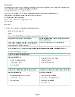
IMPORTANT:
Wall-mount the switch with network ports facing up or down (away from or toward the floor). Do not wall-
mount the switch with the ventilation holes facing up or down. (See
Installation Precautions
on page 1.)
5.
Power up the switch and connect it to your network.
6.
Configure the switch for operation on your network.
a.
Configure the PC with an IP address and subnet mask compatible with your network. The IP addressing allows the
PC to communicate with the switch through the PC web browser.
b.
Connect the PC directly to the switch.
c.
Open the PC web browser and enter the switch IP address to access the web interface of the switch. You will be
prompted to log in with a Username and Password. In the switch factory default configuration, the Username is
admin
. There is no default Password.
7.
Using the switch web interface, configure the switch as needed. For more information, see the latest edition of the
Management and Configuration Guide
for your switch at
http://www.hpe.com/networking/ResourceFinder
8.
Connect network cables to the switch as needed.
NOTE:
For transceiver connections, install and use only HPE SFP transceivers supported by the switch. See the Installation
and Getting Started Guide for your switch model at
http://www.hpe.com/networking/ResourceFinder
.
Power cords and power adapters
JL380A 8G external power adapter and power cords:
Universal inline power adapter (5066-5563)
specifications:
• AC Input Voltage: 100–240 V
• Maximum AC Input Current: 0.4 A
• AC Input Frequency Range: 50/60 Hz
• DC Output Voltage: 12 ± 10% V
• Maximum DC Output Power: 15 W
• Maximum DC Output Current: 1.25 A
AC power cord:
Country:
8121-0870
Australia/New Zealand
8121-0664
Thailand
8120-8373
China
8121-0702
India
8120-6314
Israel
8120-6316
Japan
8120-6317
South Africa
8120-8441
South Korea
8121-0963
Taiwan
Table Continued
Page 5


