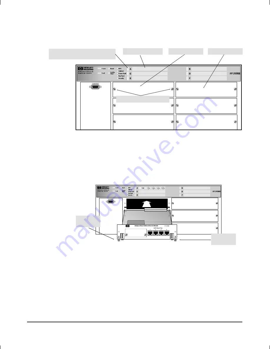
3. Holding the module by its edges—taking care not to touch the metal
connectors—position the module in front of an open slot on the
switch by aligning the edges of the module with the small grooves
near the bottom of the module slot, as shown in the next illustration.
4. Make sure the extractor handles on each side of the module are in
the open position (rotated away from the face plate), then push the
module into the slot until you feel the extractor handles contact the
switch chassis. (The handles will move slightly upwards when they
contact the chassis.)
Unscrew These Two Screws
LED Label Slot ‘‘A’’
Module Slot ‘‘A’’
Replace the blank LED label strip
with the Ethernet LED label strip
Module Slot ‘‘B’’
Figure 1.
Remove the Cover Plate from an Unused Switch Port
Extractor
Handle
Extractor
Handle
Figure 2.
Extractor Handles in the Open Position
Installation
3


