


Chapter 4
Installing and Configuring
Installing Processors and Memory
37
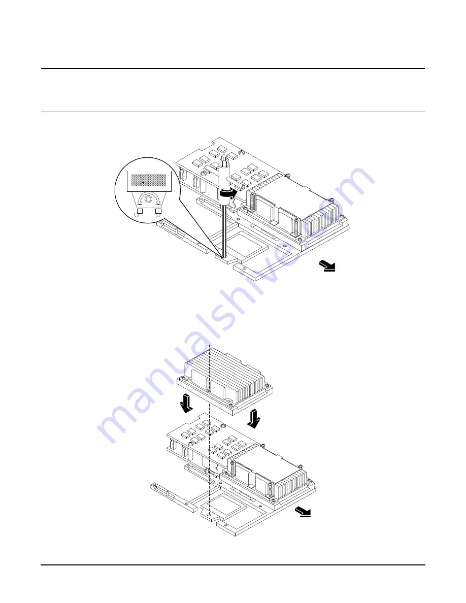
CAUTION
The zero insertion force (ZIF) socket for the processor is locked and unlocked by 1/2 of a full turn
of the 2.5 mm hex tool. The counterclockwise 180 degree rotation (1/2 turn) unlocks the socket. A
clockwise 180 degree rotation locks the socket. Attempting to turn the locking mechanism more
that 180 degrees can severely damage the socket.
Figure 4-6Unlocking the Processor Locking Mechanism
Step 4.
Place the processor and heatsink assembly over the processor socket. Use the four locator posts on the assembly to
align with the locator holes on the system board. Make certain that the connector that will mate with the processor
power pod is pointing toward the back of the chassis.
Figure 4-7Aligning the Processor Assembly
Unlocked
Front of server
Locked
Note: When properly
aligned, the connector of
the processor and heatsink
assembly will face the rear
of the chassis.
Front of server
Summary of Contents for Integrity rx1600
Page 12: ...Figures 12 ...
Page 16: ...Chapter 1 About This Document Where to Get Help 16 ...
Page 24: ...Chapter 2 Controls Ports and Indicators Rear Panel 24 ...
Page 50: ...Chapter 4 Installing and Configuring Optional Management Processor Card MP 50 ...
Page 126: ...Chapter 6 Troubleshooting Where to Get Help 128 ...
Page 170: ...Chapter 7 Removing and Replacing Components Replacing the Base Unit 174 ...
Page 176: ...Chapter 8 Parts Information Field Replaceable Parts FRU List 180 ...
Page 202: ...Index 206 ...