background image


Installation Manual 


CA294-03070 rev 00 

page 66 of 153 

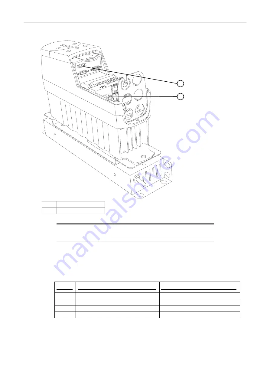
Figure 47  The Unidrive unit 


1 CTNET 

connection 

2 Encoder 

connection 


NOTE:


UD51 second encoder feedback module is not installed on all 
Unidrives. In addition, the connector to the UD51 second 
encoder feedback module is not installed on all Unidrives. 

8. 

Install all Unidrive cables as follows:   

a. 

Remove the front lower covers from the Unidrives, and insert the following 
connections (see Figure 46 and Figure 47): 

For both printing engines, there are two 8 mm power and encoder motor cables. 

b. 

Install the PE1-to-Unidrive cables as follows: 

Cable  

From end point PE1 

To end point 

CC418 

Drive motor, encoder connection  

FP1 encoder at 

24U0


CC419 

Motor drive power connector orange cable 

FP1 drive at 

24K9

, pins 2,4,6, PE, PE 

CC420 

Impression engage motor encoder 

IP1 encoder at 

25U0


CC421 

Motor drive power connector blue cable  

IP1 drive at 

25K9

, pins 2,4,6, PE, PE 

PUBLISHER-1133

2

1

Summary of Contents for Indigo Division Series

Page 1: ...ed ECO N A Security level HP confidential Contents Installation instruction details 1 Overview 6 Warranty disqualifier 7 Quick reference checklist 8 General information 17 How to use this manual 17 Packing list 17 The alignment jig 19 The parallel jig 20 Prerequisites 22 Estimated installation time 22 Special skills 22 Special jigs and tools 22 Pre installation procedure 23 Verifying site preparat...

Page 2: ... the master computer 128 Production flow 130 Install the finishing components 130 Installing the turnbar stepping plate 130 Install the main power connection and transformer 130 Initial power up 131 Emergency stop tests 136 Threading the web 138 Configure the press software 139 Install PIP and blankets 139 Testing and calibrating the press 139 Customer acceptance test procedure CATP 145 CATP speci...

Page 3: ...engine front 46 Figure 31 Leveling at the printing engine input PE2 shown 47 Figure 32 Mounting an alignment jig on the ITM end cap 48 Figure 33 Aligning the printing engines alignment jigs 50 Figure 34 Identifying the u base adjustment screws 51 Figure 35 Aligning the surveying tool crosshairs and sights 51 Figure 36 Measuring the parallelism between rollers of opposing printing engines 52 Figure...

Page 4: ...eed stepping plate rollers between stepping plate rollers 95 Figure 78 The priming unit rollers position in the ILP 97 Figure 79 Identifying the rollers 98 Figure 80 Installing the priming rollers outer and inner stations 99 Figure 81 Moving the unwinder into its final position 100 Figure 82 Leveling the unwinder 101 Figure 83 Checking the level at the unwinder exit 102 Figure 84 Aligning the unwi...

Page 5: ...tifying the slave computer connections 122 Figure 105 Mounting the slave computer and switchbox in electrical cabinet M2 123 Figure 106 Connecting a slave computer to its printing engine 124 Figure 107 Connecting the master console computer 127 Figure 108 Installing the monitor base 128 Figure 109 switching the UPS on 132 Figure 110 The web feed system 138 Figure 111 The image placement parameters...

Page 6: ...s and turnbar Install the In Line Primer ILP Installing the unwinder Install the main electrical cabling Install the slave computers and switchboxes Install the printing engine vacuum hoses Install the cooling water hoses Install the floor platform Install system components such as ink cabinets utility cabinets and writing heads Install the master console and computer Powering up the press Install...

Page 7: ... qualified personnel using lifting bars lifting straps and other specialized equipment that meet HP Indigo specifications as well as any additional requirements imposed by central and local government regulations Improper lifting may cause serious personal injury and or damage to the press or other property Do not lift the printing engines PE from the paper input or paper exit side When lowering t...

Page 8: ...nd on page 28 Use surveying tool to align u bases accurately Raise the tripod and surveying tool to 1550 0 mm U bases 40 mins 7 Install the junction bars on page 32 Install the junction bars between the two u bases 8 Mount the PE2 on page 33 Mount the PE2 on the u base Use the lifting and positioning assembly 9 install the platform on page 43 Install the platform between the printing engines 10 Mo...

Page 9: ...mmunication cable between electrical cabinets M1 and M2 and PLC in cabinet M1 23 Install the CTNET cables on page 68 Install CTNet cables between all Unidrives at electrical cabinets M1 and M2 24 Route the MPI MODBUS cables on page 69 Route the MPI MODBUS cable through the ILP connection panel to the front of PE1 and connect JTBD of the cable to PTBD of the TBD Route the remaining connector JTBD t...

Page 10: ...electrical cabinet M1 PE1 and PE2 Connect the cables to the internal battery Writing head 30 mins 30 Install the writing head on page 76 Remove writing head from box 8 Remove under plate at heater window Install and align writing head HVPS 40 mins 31 Install the HVPS on page 77 Install HVPS units and covers Roof 15 mins 32 Install the HVPS on page 77 Install roof covers Utility cabinet top cover 1...

Page 11: ...sing the parallel jig 44 level and align the ILP exit stepping plate rollers on page 94 Level and align the ILP exit stepping plate rollers 45 Install the ILP feed stepping plate on page 96 Install the ILP feed stepping plate Align and level the stepping plate to the ILP 46 install the priming rollers on page 99 Install the ILP priming rollers 47 Installing the unwinder on page 100 Position instal...

Page 12: ...n page 116 Mount and install the corian working surface Mount the monitor keyboard and mouse on working surface Web guide 10 mins 59 Adjusting the web guide on page 116 Remove the two securing screws and adjust the web guide Customer to save screws To troubleshoot refer to w3200 service manual Calibrations Utility cabinets 20 mins 60 Install the utility cabinet on page 117 Install the utility cabi...

Page 13: ... electrician to be present at startup to check mains power connections Thread web 69 Threading the web on page 138 Mount a roll at unwinder and thread to finisher according to Configure press 70 Configure the press software on page 139 Install latest version of press software with authorization codes PIP and blankets 71 Install PIP and blankets on page 139 Mount and install PIP and blankets on rel...

Page 14: ...ervice Instruction Calibrations MNU 1633 01 e Make sure that the substrate is centered at PE1 Print and check f Make sure that the substrate is centered at PE2 Print and check 10 Perform color adjustment using the paper roll supplied with the press If a different substrate is to be installed on the press perform the following a Load glossy paper on the press b From the Adjustments menu click Color...

Page 15: ...b Editor The Systab editor window opens o Expand the mmiCATopic tree p In the right window double click SpecOdLowerDeltaOsm The mmiCATopic SpecOdLowerDeltaOsm window opens q In the Saved field type 0 7 r Click OK The window closes s Double click SpecOdLowerDelta5 The mmiCATopic SpecOdLowerDelta5 window opens t In the Saved field type 0 7 u Click OK The window closes v Close the Systab Editor w Fro...

Page 16: ...e Diagnostics menu click Writing Head The Writing Head window opens ff Click the Laser Power tab gg Check that the Laser Power values do not approach the upper or lower limits 30 to 1 If the values are at either extremity perform the Machine LUT Calibration wizard from Adjustments Machine LUT Calibration 11 If necessary perform the Machine LUT using 180 lpi Testing during normal operation on page ...

Page 17: ... Installation Manual 1 3 1 Electric Cabinet 2 CA254 00322 CA271 00263 EBC 3005 01 WHS electrical cabinet M2b Keys Computer Slave 1 and 2 Network Ethernet SW1 1 4 2 2 Electric Cabinet 3 MPQ 0620 51 U base assembly 2 U base 4 CA290 05140 MPQ 0024 33 MSQ 0017 02 MJX 2427 51 MZH 0328 02 Printing engine 2 PE2 Working surface Leveler 75x150 55 Airloc Fixing bracket assembly Pipe Insulation 1 1 8 1 1 4 2...

Page 18: ...llaneous PE1 9 CA244 05941 CA245 08182 CA245 08352 Screws M8x40 flat Washers Spring Washers Cover for left ramp Left ramp assembly ILP Right ramp assembly ILP 8 of each 1 1 1 Ramp 10 CA245 01234 CA240 47210 CA245 16791 CA245 04963 ILP Air pipe black dia 12 Upper rubber roller assy ILP lower roller assy 1 2 2 2 ILP 11 5188 1250 CA240 60860 5188 4872 UW6 Unwinder for w3250 Pipe air 8mm Panel front P...

Page 19: ...ent jigs mounted 1 Sights increasing in height from PE1 to PE2 2 PE1 jig 3 PE2 jig 4 Highest sight Alignment jigs are used to adjust the forward rearward alignment of the printing engines The jigs are used with a surveying tool scope They are not identical When mounted properly the sights on the jigs increase in height going from PE1 to PE2 The increase in height allows all the sites to be visible...

Page 20: ...6 9 5 4 2 3 1 8 7 1 880 mm long extension 6 Dial 2 650 mm medium extension 7 Base 3 Extension securing screw 8 200 mm short extension 4 Dial bracket securing screw 9 V section 5 Dial bracket The jig may be extended between rollers of distances using the three extensions which are attached to the base The v section is suitable for rollers of diameter 50 79 mm whereas the dial bracket buffer and dia...

Page 21: ... the desired extension long intermediate short Tighten the handle 2 Insert the extension into the base so that the V section and the gauge are facing the same direction Tighten the two handles to secure the extension NOTE Disassembly is the reverse of the above two steps Figure 5 Mounting the v section of the Parallel jig 1 Base v section 2 Roller 3 Mount the v section on the first roller Figure 5...

Page 22: ...djust the position of the gauge fixture in the extension so that the wheel rests on the roller and coincides with the vertical centerline of the roller Tighten the handle and the lock nut 8 Slide the gauge support back until the contact touches the roller Continue sliding the gauge until the needle makes one complete turn Tighten the screw to secure the gauge support in place Prerequisites Complet...

Page 23: ... to the HP Indigo press w3250 site preparation guide for details of the floor area Unpacking the boxes 1 Before opening the boxes check that the shock and tilt sensors have not changed color to red If either of the sensors has changed color to red then the boxes were mishandled Notify the Regional Service Manager or Installation Manager immediately 2 Unpack the box containing the accessories kit O...

Page 24: ...tions 2 If any of the finishing components include electrical cabinets position that cabinet opposite its corresponding finishing component and in line with the main electrical cabinets Installing the printing engines Positioning the printing engines 1 Position the u bases as follows a Unpack the u bases and loosen the front two securing screws to remove the u base slip plates Place the slip plate...

Page 25: ...Installation Manual CA294 03070 rev 00 page 25 of 153 Figure 7 Positioning the u bases 1 PE1 u base 2 PE2 u base ...

Page 26: ...at the electrical cabinets Figure 8 Remounting the u base slip plates 2 1 5 4 4 3 1 U base slip plate 4 Securing screws 2 2 U base 5 Adjustment screws 3 Grease applied here d Remount the u base slip plates on the u bases Figure 8 Grease the u bases before mounting the u base slip plates The grease facilitates easy adjustment during the aligning procedure e Secure the slip plates with the outer scr...

Page 27: ...0 page 27 of 153 Figure 9 Adjusting the u base height 3 4 2 1 1 U base 2 U base slip plate 3 Height of 200 00 mm 4 Height adjustment screw f Adjust the u base feet to give a height of 200 0 mm from the floor to the u base top side Figure 9 ...

Page 28: ...n the PE2 u base PUB_1596 1 1 2 2 3 3 4 4 5 5 0 5 mm 0 5 mm 3 2 1 1 Sight 2 Foresight stand 3 PE2 u base g Position the foresight stand on the PE2 u base at the front left corner Figure 10 NOTE The initial position of the foresight stand is used as the reference for leveling both u bases ...

Page 29: ...urveying tool 2 1 3175 mm 125in X X X 693 0 mm 1 Position of surveying tool 2 Surveying line NOTE The surveying tool is setup on its tripod in accordance with its instruction manual at the position shown in Figure 11 h Raise the height of the tripod and surveying tool to 1550 0 mm ...

Page 30: ...g and parallel to the foresight stand Figure 12 Figure 13 Leveling the surveying tool PUB_1346 1 1 Level bubble j Adjust the level of the surveying tool until the bubble is centered in the level Figure 13 k Focus the surveying tool so that the cross target on the foresight is clearly seen and centered with the crosshairs of the surveying tool Figure 11 If necessary adjust the height of the cross t...

Page 31: ...eat step m for all the corners of the u bases Tighten the u base foot lock nuts at each corner after it is leveled o Recheck all the corners to confirm the heights Re adjust if necessary p Use a marker pen to mark the position of the u base feet on the floor Figure 14 Loosening the u base connecting rods PUB_455 1 1 Connecting rod q Loosen the four screws securing the connecting rod of each u base...

Page 32: ... a web feed door PE2 has a web exit door The lifting jig should only be used if a forklift is either unavailable or the site does not allow entry to a forklift CAUTION Each section of the lifting jig has a diagram label describing the position of the section when lifting the press Use each specific section in its correct position as labeled Make sure to adhere to all the safety warnings labeled on...

Page 33: ...e front exit service door 1 Remove these screws 2 Door lower hinge 3 Front exit service door 2 Mount the PE2 on the u base as follows At PE2 a Remove the three screws securing the upper shaft of the front exit service door frame b Remove the door by lifting it out of its frame ...

Page 34: ...or later reinstallation Figure 17 The lifting and positioning assembly 1 Orientation labels 6 Link bar 2 Support wedges 7 Maximum lifting weight label 3 Pneumatic gun connector adapter for wheel jack 8 CE label 4 Wheel jack 9 Support wedges 5 Warning label For use on horizontal surfaces only CAUTION Do not use a pneumatic gun to raise or lower the wheel jack ...

Page 35: ...e 18 Positioning the link bar under the feed side 1 Engine rear 4 Positioning label 2 Base frame 5 Feed link bar 3 Support wedges d Position the feed link bar under the base frame Figure 18 Make sure to insert the support wedges under the engine feed base frame ...

Page 36: ...ar 1 Rear electronic cabinet door 5 Support wedge 2 Support wedge 6 Exit link bar 3 Positioning label 7 Exit base frame 4 Rear engine frame e Fully open the rear electronic cabinet door Figure 19 f Position the exit link bar under the exit engine frame Figure 19 Make sure to insert the support wedges under the exit base frame Figure 19 ...

Page 37: ...serted in the lifting frame slots Figure 20 h Make sure that the link bars are inserted sufficiently to the lifting frame slots so that metal securing pegs can be fully inserted to the holes between the link bars and the lifting frames i Insert the metal securing pegs to the holes between the link bars and the lifting frames j Turn each wheel jack Figure 17 at the four corners of the lifting frame...

Page 38: ...t wedge Figure 22 Placing the leveling pads on the u base 1 Leveling pad slots 4 Leveling pad slots 2 U base cover 5 Leveling pads 3 Allen M10 height adjustment screw 6 k Mount four leveling pads Figure 21 at the four corner slots of the u base Figure 22 Make sure that the pads are mounted centrally on the slotted areas of the u base cover as shown in Figure 22 ...

Page 39: ... press for easy access l Make sure that the leveling pads are at their default height Figure 21 4 If not use an Allen M10 key to lower or raise the height adjustment wedges to their default level Figure 21 Figure 23 Moving the raised engine to the u base 1 Front lifting frame 3 Leveling pads 2 U base 4 Direction of lifting jig and engine over u base ...

Page 40: ...ad 5 Leveling pads 3 U base 6 Exit base frame underside slot m Carefully move the lifting jig and press over the u base until the feed and exit base frame underside slots Figure 30 are aligned correctly with the top surfaces of the leveling pads Figure 23 and Figure 24 If necessary move the u base to correctly align the underside slots with the leveling pads top surfaces ...

Page 41: ...rinting engine raised above u base 3 Printing engine correctly positioned on leveling pads and u base 2 Correct position of leveling pads 4 Correct position of leveling pad n Turn each wheel jack Figure 17 an equal number of turns in steps of 3 4 turns to lower the engine on the leveling pads and u base Figure 32 Figure 25 ...

Page 42: ...26 Engine mounted on the u base 1 Position of link bar secured against press frame beam 4 Leveling pad 2 Frame slot 5 Leveling pad 3 U base 6 Frame slot o Make sure that the pads are correctly aligned within their slots on the u base and under the press Figure 26 ...

Page 43: ...from the printing engine The printing engine and u base should appear as shown in Figure 27 CAUTION When transporting the printing engine secure the engine to the u base using the securing brackets Figure 27 3 To install the platform between the two printing engines a Insert the platform between the two engines b Use two bolts washers and nuts to install the platform at each engine side ...

Page 44: ...rnbar end roller 7 Front connection bracket 2 Turnbar idler 1 8 Rear connection bracket 3 Turnbar air pressure valve and dial 9 Turnbar idler 2 4 Turnbar air vacuum control valve 10 Turnbar idler 3 5 Turnbar lateral adjust control 11 Turnbar cross lower roller 6 Air pressure supply 12 Turnbar air pressure cross upper roller ...

Page 45: ...s in the output assembly of the PE2 WHS Figure 29 Mounting the PE1 At the PE1 1 Repeat step 2 on page 33 for the PE1 2 Use a manual forklift to move the presses and u bases to their fixed marked positions on the floor Make sure to move PE1 close to PE2 but leave a gap of at least 1 cm between the engines 3 Use an Allen M6 key to verify the tightness of the junction bar securing screws between PE1 ...

Page 46: ...top bracket to secure the door Use the original screws to secure the bracket Leveling the printing engines Figure 30 Using a level at the printing engine front PUBLISHER 1022 1 3 2 1 1 Front base 2 Level 3 Leveling bar jig 8 To level each printing engine do the following Figure 30 a Remove the grounding cable screws at the front base Place the jig and level on the flat surface of the front base ...

Page 47: ...e position and level of the engine A long crow bar to slightly adjust the position of the engine 2 mm spacers placed between the pads and the engine frame Use a lift jack to slightly raise the engine and insert the pads Level to an accuracy of 0 00 0 01 mm c After the printing engine is level make sure that the four wheels are not in contact with the ground If not use the pads to lift the wheels e...

Page 48: ...centerlines of the printing engines are collinear Figure 32 Mounting an alignment jig on the ITM end cap 1 ITM bearing housing plate 3 Sights 2 Alignment jig adapter 4 Alignment jig mounted on ITM end cap CAUTION When installing the alignment jigs make sure not to damage the ITM lamp or any wires exiting from the lamp NOTE See General information on page 17 for details on mounting and using the ji...

Page 49: ...y removed in the same holes Make sure of the following The ITM heater cable is routed through the adapter inner groove The adapter is suitable for the plate and there is no gap between the plate and the adapter On some engines three of the plate securing screws protrude and only the specific adapter suitable should be used c Mount the PE1 alignment jig P N MJX 3055 51 on the ITM end cap of PE1 Mak...

Page 50: ...Installation Manual CA294 03070 rev 00 page 50 of 153 Figure 33 Aligning the printing engines alignment jigs 1 Surveying tool 2 Line of sight 3 Alignment jigs 4 PE front ...

Page 51: ...wards the rear and loosening them moves it towards the front Each turn of the u base slip plate inner screws moves the printing engine by 0 3 mm e Adjust the inner screws on the u base slip plate of each printing engine until the sights on both alignment jigs are aligned with the crosshairs in the surveying tool Figure 33 Figure 35 They should be aligned such that the crosshairs of the surveying t...

Page 52: ...he section General information on page 17 b Place the gauged end of the jig on idler 3 of PE1 c Move the jig along the length of the rollers Figure 36 Note the difference in the readings between the front and the rear If the readings differ by more than 0 02 mm then adjust the u base slip plate screws shown in Figure 34 to correct the alignment d Repeat step c until the difference between the fron...

Page 53: ... bracket 2 Rear link bracket Figure 38 Mounting the front link bracket 1 PE2 5 Plate bracket 2 PE1 6 Front corner bracket 3 Joining screw 7 M6 Allen screws 4 19 mm bolts NOTE Use caution when installing the link brackets as the printing engines can move if the link bracket is closed too tightly ...

Page 54: ...n bracket 1 Turnbar 4 Rear connection bracket 2 Turnbar idler 3 5 Idler extended shaft 3 Turnbar idler 2 1 Mount the front and rear connection brackets on the extended shaft of idler 3 Figure 39 2 Lower the turnbar towards PE2 Make sure that the rear and front connection brackets face towards the PE2 input rollers ...

Page 55: ...ont connection bracket 4 Upper screw securing the idler 5 Lower screw securing the front connection bracket 3 Insert and slide the input idler to both the front connection bracket and the PE2 input rollers front side wall Figure 40 4 Secure the idler with two M5 wide head bolts P N MBS 0820 10 upper screw P N MBS 0816 10 lower screw at the upper screw holes Figure 40 ...

Page 56: ...NOTE Before tightening all the screws to secure the turnbar make sure that all of the turnbar rollers move without friction 7 Holding the turnbar in position tighten the screws 8 Connect the turnbar air hose to the turnbar air pressure air valve 9 To connect the printing engines to each other a Mount the front link bracket Figure 37 and Figure 38 Install the two 19 mm bolts and the two M6 Allen sc...

Page 57: ...ge 57 of 153 d Check the parallelism between the printing engine rollers using the parallel jig Realign if necessary e Tighten the joining Allen screw of the front link bracket f Tighten the screws securing the u base connecting rods Figure 14 ...

Page 58: ... floor plates Figure 42 Connecting the main electrical power in the electrical cabinet 3 2 4 1 1 Locking bracket 2 3 Main power connector 4 Direction of closing locking bracket 2 To install mains power connectors Figure 42 a Insert the cable connector to its female connection at the cabinet b Pull and turn the locking bracket until the mains power connector is locked ...

Page 59: ...abinet cables to the inner wall channel bracket attached to the wall of the electrical cabinets Figure 43 Use the support back plate to support the rear of the cable Insert the cable bracket at the front of the cable IMPORTANT Where a cable consists of a number of wires the black wires are labeled 1 2 3 4 etc in white on the wire at the insertion ends Some cables are labeled U VV WWW XXXX instead ...

Page 60: ...Installation Manual CA294 03070 rev 00 page 60 of 153 Figure 44 Components of electrical cabinet M1 NOTE Location of the connectors may vary ...

Page 61: ... PE EHE 4400 51 CC400 400 VAC 3 phase power cable for PE1 at JX8 X8 connections 1 2 3 N PE CA261 10950 20F8 connector pins 1 3 PE to cabinet fans 1 phase 24 V power supply for electrical cabinet M2 at JX36 Old cable EHE 4406 51 CC406 EHE 4438 51 CC438 400 VAC 3 phase power cable for PE2 at JX9 X9 connections 1 2 3 N PE CA261 10930 X31 connector pins 1 3 PE at 15F1 UPS connection for PE1 JX31 Pins ...

Page 62: ...le connection Main AC power to line filter in PDU CA261 10640 3 phase power supply for PE2 at JX9 PE2 3 phase 400 VAC power cable connection Main AC power to line filter in PDU 6 Install the electrical cabinet M2 to PE1 PE2 engines according to the following Cable From end point elect cab M2 To end point PE1 or PE2 Notes CA261 10550 Cable from JX31 Pins L N PE Power cable to PF1 PDU CA261 10560 Ca...

Page 63: ...434 Electrical cabinet M2 X62 connector Junction box 7 Install the electrical cabinet M1 to master console cables as follows Cable From end point To end point Notes CC77A RS 232 control for UPS Master console PC CC27B UPS power connection for master console at electrical cabinet M1 X30 pins 3 4 5 Master console cabinet power in multiple sockets CC439 Interlock interface to master e stop electrical...

Page 64: ...eft side connector J4 top plug 4X Master console switchbox connector J2 to plug 3X W190 From master console switchbox connector P1 to plug 1X Master PC on board Ethernet connection See Figure 107 connect to onboard network connection No 4 CC70 LAN from master network interface card Customer wall CC69 Modem from master computer Customer wall ...

Page 65: ...5 interface module 2 CTNET connection 3 MODBUS connection 4 Connector to UD51 second encoder feedback module 5 Cable securing bracket 6 UD51 second encoder feedback module 7 Unidrive encoder connector 8 Elec cab to elec cab power connectors nos 1 11 9 Elec cab to elec cab power connectors nos 21 31 10 Unidrive main unit 11 Mains power connector 12 Mounting bracket and break resistor unit with ther...

Page 66: ...ont lower covers from the Unidrives and insert the following connections see Figure 46 and Figure 47 For both printing engines there are two 8 mm power and encoder motor cables b Install the PE1 to Unidrive cables as follows Cable From end point PE1 To end point CC418 Drive motor encoder connection FP1 encoder at 24U0 CC419 Motor drive power connector orange cable FP1 drive at 24K9 pins 2 4 6 PE P...

Page 67: ...e 28K9 pins PE PE 2 4 6 CC444 Turnbar feed motor FX encoder 29K0 CC445 Turnbar feed motor power blue cable FX drive 29K9 pins PE PE 2 4 6 9 Install the PE1 to PE2 cables as follows Cable From end point To end point CC9B Electronic gearing PE2 ESBPRO J53 connector PE1 ESBPRO J65 connector CC114A PE2 service door interlock PE1 service door interlock PE1 ECN Electronic engage cable PE2 ECN Electronic...

Page 68: ...028 exit nip feed FE controllers 5 pin connection at UD75 Electrical cabinet M2 U028 exit nip feed FE Electrical cabinet M2 U027 IMP engage of PE2 IP2 controllers 5 pin connection at UD75 Green CTNET cable connects between all Unidrives from UW to FX to FE to IP2 to FP2 to IP1 to FP1 Electrical cabinet M2 U027 IMP engage of PE2 IP2 Electrical cabinet M2 U026 PE2 feed FP2 controllers 5 pin connecti...

Page 69: ...le terminator should be turned off Connection is on top of cable 11190 CA294 11200 CC428 Purple Profibus Cabinet M2 PLC connection 60A2 Cabinet M1 53A5 connection Verify connection CA294 11200 CC428 Purple Profibus Cabinet M2 PLC connection 80A2 Cabinet M1 53A5 connection Verify connection CA294 11200 CC428 Purple Profibus Cabinet M2 PLC connection U3 VB2 Cabinet M1 53A5 connection Verify connecti...

Page 70: ...e 50 Installing the vacuum hoses and adaptors PRESSSIDEVIEW ELECTRONIC CABINETS 1400 mm PAPER ENTRY SLOT 170 200 BLOWER COOLER UNIT INK UNIT 1040 mm PRINTING ENGINE 540 mm 1100 mm 400 mm STAGE TOP LEVEL REMOVABLE TILES 600 mm GROUND LEVEL BASE FEET 1490 mm 1350 mm 1 1 V junction adapters ...

Page 71: ...ve the panel and save it and the screws for later reinstallation 2 Connect the four large vacuum hoses to the four blowers in electrical cabinets M1 and M2 See Figure 50 Figure 51 Routing vacuum hoses to PE1 PUB_6869 1 1 Four hoses inserted to air ducts at the vacuum box 3 Route the short 2m hose connected to the upper blower in electrical cabinet M1 to the vacuum box in PE1 Figure 50 and Figure 5...

Page 72: ...nstalled The floor platform must meet the specifications detailed in the HP Indigo press w3250 site preparation guide The customer engineer should inform the floor platform installers to start installing the floor at the unwinder and ILP positions When installing the floor near the press the installation should either be started at the corners of the press or at the wall depending on the convenien...

Page 73: ...er valves until the water hose connections between the chiller printing engines and ink cabinets are verified as correct Figure 53 Chiller pipe routing Europe Chiller External Drainage Tank Engine No 2 Blower Engine No 1 Blower 160 cm 63 inches External wall 2 pipe Flow rate gauge Temperature gauge 2 main ball valve 1 ball valve Barb fitting 1 inside diameter 1 flexible tube installed by HP 1 pipe...

Page 74: ... when chiller water exit is below press level 2 To connect the cooling water hoses to the press use the following adapters and tools a Two hose 1 5 pipe fasteners BSP and four pipe clamps for inlet and outlet water connections b A single hose 0 5 pipe fasteners and two pipe clamps c Teflon tape d Two 90 elbow connections 3 Perform all connections of the cooling water hoses to the press and make su...

Page 75: ...PS units may differ in their rear panel details However their general features will remain similar as will their cable connections Figure 55 The rear UPS panel UPS_R 7 6 5 4 3 2 1 1 COM SNMP RS232 connection 2 Output breaker button 3 Output to printing engine 4 Breaker button 5 Input from PC 6 Input breaker 7 Mains power supply ...

Page 76: ... UPS CC234 Output cable from slave 2 PC Input connection at the 2 nd UPS CC235 Output cable from master PC Input connection at the 3rd UPS 2 Make sure that the cables are connected between the UPSs the PEs and the electrical cabinets Install the writing head 1 Carefully remove the writing head P N CA270 00101 from Box No 8 2 Remove the parameters diskette from the top of the writing head and save ...

Page 77: ...ge Power Supply Figure 57 HVPS installation HVPSUNIT CDR 2 3 4 1 6 5 1 HVPS top cover 2 HVPS rear cover 3 Electrical cabinet side door 4 Baseplate 5 Electrical cabinet 6 HVPS front cover Figure 58 The HVPS cage assembly ex1 2 1 4 3 1 Top cover 2 Front cover 3 Baseplate 4 Rear cover ...

Page 78: ...r M6 16 Allen screws with washers and spring washers to install the HVPS on the baseplate Figure 59 Figure 60 Installing the baseplate on the press HVPSCAGE2 CDR 1 2 1 Baseplate 2 Screws securing baseplate to press 2 each side 2 Use four M5 20 Allen screws with washers and spring washers to install the baseplate and HVPS on the press Figure 57 and Figure 60 3 Place the sponge filter on top of the ...

Page 79: ...r to the baseplate Figure 61 5 Install the HVPS front cover Figure 62 Connecting the cables to the HVPS DANGER HIGH VOLTAGE WARNING HVPSFANS CDR OPT 2 SCR 3 GND 24VDC J3 J2 HVPS I F OPT 1 BID 7 BID 6 BID 5 BID 4 BID 3 BID 2 BID 1 SCR 2 SCR 1 ITM 2 3 1 1 Fans 2 J2 connector 3 Cage 6 Connect the cables to the HVPS Figure 62 7 Install the HVPS rear cover Install the roof covers Install the two roof c...

Page 80: ...ID units with imaging oil and a lint free cloth f Install the BID units Make sure that the BID units are thoroughly clean before installing them If necessary re clean the BID units g Install the Ametek filters Unpacking the ILP unwinder utility cabinets and ink cabinets 1 Unpack the ILP unwinder two utility cabinets and two ink cabinets 2 Lift and move the ILP unwinder utility cabinets and ink cab...

Page 81: ...fer roller 4 Outer station simplex primer No 4 SP4 20 Inner station duplex primer No 1 DP1 5 Outer station simplex primer No 3 SP3 21 Idler No 10 6 Outer station simplex primer No 2 SP2 22 Upper buffer rollers 7 Outer station simplex primer No 1 SP1 23 Idler No 9 8 Idler No 3 24 Inner station duplex primer No 2 DP2 9 Idler No 4 25 Idler No 8 10 Idler No 13 26 Upper driver roller 11 Idler No 2 27 U...

Page 82: ...tepping plate 6 Adjust the feed and exit stepping plates 7 Install the unwinder 8 Install all cables to from the Electrical cabinet M1 ILP and unwinder Positioning the ILP 1 Move the ILP on the floor platform to the input side of PE1 The ILP should be supported by its castors enabling it to be rolled into position Figure 64 Distinguishing the ILP feed and exit stepping plate assemblies 1 ILP feed ...

Page 83: ...zed balled end Allen keys 1 Release the two ILP feed and exit stepping plate assemblies from the ILP stepping plate pallet P N CA245 01234 by releasing the stepping plates securing bracket Use an 6 mm wrench to remove the nuts securing the four screws 2 To install the ILP exit stepping plate assembly Figure 64 a Set the ILP close to its final position Figure 65 Mounting the ILP stepping plate asse...

Page 84: ...E ASSEMBLY 4 5 3 2 1 6 7 1 Lower bracket 5 ILP 2 Upper securing screw 6 Lower securing screws 3 Upper frame 7 Stepping plate assembly 4 Upper securing screw c Install the exit stepping plate assembly to the ILP using four Allen M5 screws washers and spring washers Figure 66 Two screws are inserted at the upper frame and two within the lower bracket slots ...

Page 85: ...xit cover on the exit side stepping plate assembly 2 1 1 Exit cover 2 Exit side stepping plate assembly d Mount the ILP exit cover on the ILP exit side stepping plate assembly Figure 67 NOTE Make sure that the PE1 web entrance cover is installed before proceeding with the ILP alignment ...

Page 86: ...ate assembly with the press Figure 68 a Move the ILP closer to the PE1 feed b Align the ILP exit cover side with the PE1 web entrance cover side c Make sure that the gap between the ILP exit cover and the web entrance cover at PE1 is approximately 4 5 mm If not adjust the position of the ILP until the gap between the covers is 4 5 mm d Remove all the packing material from the ILP and stepping plat...

Page 87: ...he cover Place aside temporarily e Align the center of the stepping plate rollers with the PE1 input rollers f Remount the ILP exit cover g Place a meter ruler or straight bar along the stepping plate front edge and extend it to touch PE1 Figure 69 h Measure the distance between the stepping plate front edge and the PE1 front wall The distance should measure 30 mm If not adjust the position of the...

Page 88: ...without touching the ILP exit side Figure 64 Figure 70 Unlocking the ILP alignment plates 1 1 1 Alignment plate locking screws x6 6 Open the front and rear ILP doors 7 Release do not remove the six ILP alignment plate locking screws Figure 70 8 Lower the four ILP feet until the castors are approximately 5 mm above the floor platform and the feet touch the floor ...

Page 89: ...nt frame securing screws 6 ILP feed stepping plate assembly 14 Position of ILP rear frame securing screws 7 ILP front foot 15 ILP exit stepping plate assembly 8 Height adjustment nut NOTE There are two sets of push pull screws Figure 71 The outside screws of each set are the push screws The inside screws are the pull screws The ILP moves forward backward 1 mm for each turn of a screw 9 To level an...

Page 90: ...ng plate assembly feet shown raised 2 each assy b Use a 20 mm wrench to release the upper nut securing the lower height adjustment nut Figure 72 c Turn the 20 mm height adjustment nut clockwise to lower the feet until the ILP wheels are just raised by 2 3 mm NOTE Two persons will be necessary for the next procedure ...

Page 91: ...91 of 153 Figure 73 Leveling the ILP 1 ILP feed frame 2 Leveler d Place a leveler at the feed and exit frames and measure the deviation from true level Figure 73 Measure the level to an accuracy of 0 0 0 1 mm e Repeat step d above at the exit ILP ...

Page 92: ...t idler No 3 Figure 63 another person should raise lower the two feet 20 mm height adjustment nuts until the feet rest on the floor and the ILP is level Measure the level to an accuracy of 0 0 0 1 mm If necessary use a jack to raise the frame and place 20 x 20 cm x 2cm spacer plates under each foot of at the ILP feed At the ILP exit h Repeat step g above placing a leveler on idler No 10 Figure 63 ...

Page 93: ...her complete turn and tighten the locking nuts At the ILP exit k Repeat step g above placing a leveler on the idler No 10 Figure 63 and adjust the two feet 20 mm height adjustment nuts until accurately leveled Measure the level to an accuracy of 0 0 0 1 mm l Tighten the six leveling screws until just tight and Then turn the adjustment nuts one further complete turn and tighten the locking nuts 10 ...

Page 94: ...tment screw 10 PE1 input idler No 2 12 To level and align the ILP exit stepping plate rollers Figure 76 For each roller a Place a leveler on the roller and verify that the roller is level at the front and rear b Reconfigure the parallel jig for the intermediate configuration Refer to the section General information on page 17 c Place the Parallel jig between the PE1 input idler No 2 and the roller...

Page 95: ...eb feed direction Figure 77 The adjustment screws are locked with setscrews f Reconfigure the parallel jig for the short configuration Refer to the General information on page 17 Use the Parallel jig in order to measure the variation in distance between the two stepping plate rollers as shown in Figure 77 Mount the Parallel jig between the two rollers g Loosen the Allen M5 front and rear adjustmen...

Page 96: ... the ILP feed stepping plate between the Unwinder position and the ILP as described in step 2 on page 83 14 Repeat step 4 on page 86 to align the ILP feed stepping plate rollers 15 Repeat step 12 on page 94 to level the ILP feed stepping plate rollers Place the Parallel jig between the unwinder lower roller and the stepping plate rollers ...

Page 97: ...ller 2 SP2 lower rubber roller 5 Simplex priming roller 3 SP3 intermediate roller 12 Duplex priming roller 3 SP3 intermediate roller 6 Simplex priming roller 2 SP2 lower rubber roller 13 Duplex priming roller 4 SP4 upper rubber roller 7 Simplex priming roller 1 SP1 reservoir roller 14 Duplex priming roller 5 SP5 impression roller The priming unit consists of two priming stations Each station consi...

Page 98: ...r and outer station rollers is similar The order of the rollers installation is as follows refer to Figure 78 and Figure 63 1st Rubber roller SP4 or DP4 2nd Rubber rollers SP2 and DP2 CAUTION Take care not to damage the priming surface of the rubber rollers They are very delicate and can be damaged easily The rubber rollers should be supported by their shafts either in their shipping box or in the...

Page 99: ...d door b Remove the outer station priming roller mount clamps Place them aside on a flat clean surface c Mount the SP2 rubber and secure it with the clamps d Mount the SP4 rubber roller and secure it with the clamps e Open the ILP top cover f Remove the inner station priming roller mount clamps Place them aside on a flat clean surface g Mount the DP2 rubber roller and secure it with the clamps h M...

Page 100: ...e 81 Moving the unwinder into its final position 1 Unwinder v6 2 Pallet jack 2 Use a pallet jack to move the unwinder into position near the input side of the ILP to a distance of between 30 40 cm from the ILP feed stepping plate assembly CAUTION When moving the unwinder make sure to place the pallet jack under the frame as shown in Figure 81 Otherwise the unwinder will be damaged ...

Page 101: ...er rollers Figure 82 Leveling the unwinder 1 Leveler 3 Unwinder 2 Unwinder fixed roller 5 Place the level on top of a fixed roller at the position shown in Figure 82 Use an M5 Allen key to raise or lower the leveling pads until the unwinder is level to 0 0 0 1 mm NOTE When leveling the unwinder use the 2 mm spacers to compensate for uneven floor height If a spacer cannot be inserted because the un...

Page 102: ...k the level at the unwinder exit upper roller shown in Figure 83 If necessary readjust the height of the leveling pads until the unwinder is level at all positions If necessary slightly loosen the unwinder exit panel screws and readjust the position of the unwinder exit panel Figure 83 Tighten the unwinder exit panel screws to secure the panel 8 Verify that the unwinder is 200 mm from the ILP feed...

Page 103: ...tween the unwinder exit upper roller and the stepping plate roller shown in Figure 84 Mount the Parallel jig between the two rollers b Move the Parallel jig from front to back to accurately align the unwinder exit upper roller Figure 84 Make sure that the rollers are aligned to an accuracy of 0 00 0 01 mm If necessary i Remove the Parallel jig ii Loosen the unwinder exit panel securing screws iii ...

Page 104: ...ve the jig along the length of the rollers Note the difference between the readings at the front and rear 13 If the difference between the readings is more than 0 1 mm 0 05 then readjust the position of the unwinder 14 Re check the level of the unwinder Re adjust if necessary 15 Re check the alignment of the unwinder to the ILP using the Parallel jig Re align if necessary Unwinder electrical conne...

Page 105: ... panel MPI connection at PLC 53A1 Route the cable from the ILP under the floor to the PE1 and PE2 exits CA261 11040 ILP priming motor power at JX22 Connection at JX22 Cable labeled 1 46 05 CA261 10880 ILP Ametek power at JX43 Connection at JX43 and DA J2 Cable labeled 1 46 05 CA261 09210 ILP Ametek control at JX2 Connection at JX2 CA261 10900 ILP 24 VDC at JX57 Also connection at JX59 Connection a...

Page 106: ...ure 86 Install cable securing clamps at the ILP 1 Rear inner ILP 4 Securing clamps 2 Cables from ILP assemblies to cabinet M1 and PE1 5 ILP rear panel 3 Clamp rail 6 Cable labels 4 Install the cable securing clamps on the clamp rail as shown in Figure 86 a Arrange the cables according to the cable securing panel labels shown in Figure 86 b Mount securing clamps on each cable to secure the cable in...

Page 107: ... M3 securing screw 6 Securing screw 3 Securing screw 7 Top Allen M3 securing screw 4 ILP rear panel 5 Make sure that the connections to the ILP appear as shown in Figure 87 a Slide the cable securing panel on top of the cables and tighten the two securing screws b Remove the two top Allen M3 screws securing the top of the ILP rear panel ...

Page 108: ...8 Connection the air supply at the ILP 1 ILP front 2 Air outlet to PE connection 3 Air Input connection 4 Air outlet to unwinder At the ILP front 1 Connect the following air hoses at the ILP front a Input hose from mains air supply to Inlet connection b Long outlet hose from Outlet to PE connection to PE1 c Long outlet hose from Outlet to UW connection to the unwinder ...

Page 109: ...air hose from the ILP 1 Air hoses 4 PE2 ILD air pressure dial 2 PE1 air manifold 5 PE1 ILD air pressure dial 3 PE2 air manifold 2 Route the Outlet to the PE1 air supply manifold as follows Figure 89 Around the back of the ILP Under the PE1 to the front of the engine air manifold ...

Page 110: ... 5 Web guide air pressure dial 2 T junction 6 ILD air pressure dial 3 Air output to PE2 7 Web guide air input connection 4 V junction adapter 8 Air manifold At the PE1 air manifold 3 Install the hose to the PE1 air manifold Figure 90 a Fit a T junction to the end of the hose b Fit a v junction adapter in the top outlet of the T junction ...

Page 111: ...LD dial regulator To the PE1 air manifold rear input to the Web Guide At the PE2 air manifold 4 Repeat step 3 above at the PE2 engine At the parallel outlet of the T junction insert a stopper 5 Connect the unwinder air supply hose to the unwinder Figure 91 Installing the safety cover on the ILP rear panel 1 Securing screws 3 Securing screws 2 ILP rear panel safety cover 6 Install the ILP rear pane...

Page 112: ...8363 1 2 3 1 ILP vacuum hose 2 Hose securing band 3 ILP vacuum hose adapter 1 Install the ILP vacuum hose adaptor to the ILP using four screws Figure 92 2 Route the hose connected to the lower blower in electrical cabinet M1 to the vacuum hose connection at the rear of the ILP Figure 92 3 Mount the hose securing band to secure the hose to the adapter ...

Page 113: ...Installation Manual CA294 03070 rev 00 page 113 of 153 Installing the ink cabinets Figure 93 The 4 color configuration front view INK_FRONT 1 C M Y K Figure 94 The 7 color configuration front view ...

Page 114: ...e 6 Grounding cable 13 J30 7 Guard bracket Install each ink cabinet as follows 1 Fill the ink tanks with imaging oil and install the ink pumps 2 Install the ink tank assemblies in the ink cabinet 3 Install the ink cans in the proper order Figure 93 and Figure 94 4 Fill the imaging oil reservoir with imaging oil 5 Connect the following cables between the printing engine and the ink cabinet Figure 9...

Page 115: ...ure 95 7 Connect the two cooling water hoses to the ink cabinet Figure 95 8 Connect the black plastic imaging oil tube to the ink cabinet Figure 95 9 Connect the solid add compressed air tube to the ink cabinet Figure 95 10 Remove the front cross panel above the ink cabinet Figure 96 Mapping the BID hoses from the ink cabinet to the BIDs C K M 5th Y 6th 7th NOTE The BID hoses are labeled ...

Page 116: ...y push the working surface into place 15 Secure the working surface to the ink cabinet with four screws from inside the cabinet Figure 95 16 Connect the grounding cable to the printing engine frame 17 Install the keyboards mice and LCD monitor at the printing engines Adjusting the web guide Figure 97 Removing the transport securing screws 1 2 1 Transport screws in post installation position 2 Orig...

Page 117: ...t 1 Mount and install the top cover on the utility cabinet Figure 98 Hinging the utility cabinet to the printing engine BLR CAB 3 5 2 1 4 1 Printing engine 4 Cooling water from chiller 2 Utility cabinet 5 Cooling water to chiller 3 Hinge 2 Move the cabinet into position and connect the lower hinge Figure 98 ...

Page 118: ... SOLID ADD COMP AIR POWER CABLE CONTROL CABLE OUTLET HOSE INLET HOSE 3 Connect the following hoses from the utility cabinet to the printing engine Figure 99 Cooling water in Cooling water out Solid add compressed air Impression drum cooling drain Vacuum Air flow 4 Connect the control cable and power cable to the utility cabinet Figure 99 ...

Page 119: ...gure 100 Closing the utility cabinet on the sealing gasket VOC 484ng 1 2 1 Sealing gasket 2 Utility cabinet 5 Carefully close the utility cabinet The utility cabinet should close smoothly and press against the sealing gasket to create a proper seal Figure 100 ...

Page 120: ...height of the utility cabinet VOC 429 2 1 1 Locking nut 2 Adjusting nut 6 If the utility cabinet does not seal properly with the gasket adjust the castors as necessary to create the seal and align the unit with the printing engine Figure 101 7 Install the utility cabinet top cover ...

Page 121: ...8 101 23 POPI WHIF 192 168 101 24 POPI WHIF 192 168 101 14 External LAN To Slave 1 192 168 111 1 ON BOARD 192 168 101 12 To Diva Master 192 168 111 2 Cross To Slave 2 192 168 112 1 To Diva Master 192 168 112 2 Cross The internal and external networks are configured as shown in Figure 102 Figure 103 The switchbox unit HUB The switchbox is an unmanaged 10 100TX unit with 1K MAC addresses and an inte...

Page 122: ...computer connections HP C ompute r xw42 00 5 000 1 2 3 4 5 7 8 9 10 11 12 13 15 14 6 1 Customer LAN 9 Mouse 2 VCORN III 10 Power 3 COM 2 port 11 Keyboard 4 VGA graphics monitor 12 COM 1 port 5 Internal LAN 13 USB ports 6 Audio out 14 RIP server LAN 7 Audio in 15 Modem 8 LPT1 Parallel Port ...

Page 123: ...Mouse and keyboard connections 2 Software dongle master computer only 3 Monitor connection 4 Writing head J10 RS 232 G Link connector 5 Switchbox 6 Computer shelf 7 Modem connection 8 External LAN connection 9 On board network connection 10 Audio connection 11 COM 1 connection 12 COM 2 connection 13 Cable routing to allow computer shelf to close correctly 14 Power connection ...

Page 124: ...nit 7 Connector bracket Each printing engine is connected to a networked computer which is installed in electrical cabinet M2 Each computer acts as a slave within the internal network of the press The master console has a computer that is the master for the two slave computers 8 Install each slave computer in electrical cabinet M2 as follows see Figure 105 a Pull out the computer shelf b Mount the...

Page 125: ... computer connectors panel PC video output Figure 106 Electrical cabinet M2 slave 1 PC video port Figure 103 3 CC48 PE1 writing head WHIF board J7 connection Electrical cabinet M2 slave 1 PC J1 G Link cable Figure 103 16 CC52 PE1 front wall computer connectors panel PC keyboard and mouse Figure 106 Electrical cabinet M2 slave 1 PC keyboard and mouse Figure 103 9 and 5 CC55 PE1 cable consisting of ...

Page 126: ...ad WHIF board J7 connection Electrical cabinet M2 slave 2 PC J1 G Link cable Figure 103 16 CC52 PE2 front wall computer connectors panel PC keyboard and mouse Figure 106 Electrical cabinet M2 slave 2 PC keyboard and mouse Figure 103 9 and 5 CC55 PE2 cable consisting of three cables Main PC power Figure 103 8 Main switchbox power Electrical cabinet M2 fan power CC54A Molex cable connection See EHE ...

Page 127: ...rt 2 Computer frame lock 10 USB connection port 3 Mouse connection 11 Sound card connections 4 Onboard Intel network connection to customer network 12 COM 2 port 5 Monitor connection 13 LPT1 and dongle connection port 6 External LAN 14 COM 1 port 7 Modem ports 15 Keyboard connector 8 2 port Adaptec local network card connections to slaves 16 Mains power cable connector The master console consists ...

Page 128: ...CC61A N A N A To Master N A CC60A CC61A Power 2 Place the keyboard and mouse on the working surface Figure 108 Installing the monitor base 1 1 Install screws here 3 Using the screws provided connect the monitor base to the monitor Figure 108 4 Pass the keyboard and mouse cables down through the slot to the computer and connect the cables to the computer 5 Connect the power cable to the LCD monitor...

Page 129: ...rom the onboard Ethernet at master PC to J5 8 Connect the gray X54 power enable emergency stop cable from electrical cabinet M1 as follows One connector to the power enable switch connector inside the master console cabinet at CC439 One connector to the cable on the base of the master console monitor ...

Page 130: ...finisher installation according to the customers design and Site Preparation Guide Installing the turnbar stepping plate 1 Install the turn stepping plate over the turnbar assembly using four Allen M6 screws and washers Install the main power connection and transformer The press should be hard connected to the mains by a qualified local electrician in accordance with local safety regulations The c...

Page 131: ...h is off b External main cabinet switch is off c UPS s are switched off d All the printing engines are turned off Make sure that all switches in the printing engines and PFU are turned off e the two writing head switches are off f Connector cables JX9 JX8 and JX4 are connected g All cabinet M1 and M2A circuit breakers and isolators are turned off NOTE When testing the 3 phase mains power at a circ...

Page 132: ...rned on turn the Internal Mains Cabinet Supply Isolator switch at 20S0 on The three green LEDs L1 L2 and L3 on the front of cabinet M1 should light 7 Turn the circuit breaker 11F2 on WARNING The system is electrically alive Take care not to touch any live parts inside the electrical cabinets 8 Verify the 3 phase main power voltage at the mains power supply The voltage should be 400 V between groun...

Page 133: ...G8 green LED is ON 24V Power Supply For all Electrical cabinets 14 Turn the circuit breakers20F8 1 on Make sure that the PLC LEDs are lit The I O 60A0 60A2 LEDs do not light at this stage 24V Power Supply For both electrical cabinets Figure 44 and Figure 45 15 Turn the following circuit breakers on a 20F3 1 b 43F1 c 22F7 16 Check that the Emergency LEDs at 33K8 33K9 33K10 33K11 switch on a Turn th...

Page 134: ...ake sure that the Cabinet Fan works correctly Make sure that the Power Supply 20G8 green LED is on 24V Power Supply For all Electrical cabinets 26 Turn the circuit breakers20F8 1 on Make sure that the PLC LEDs are lit The I O 60A0 60A2 LEDs do not light at this stage 24V Power Supply For both electrical cabinets Figure 44 and Figure 45 27 Turn the following circuit breakers on a 20F3 1 b 43F1 c 22...

Page 135: ...1 j CBT1 2 k CBT0 3 l CBT0 4 m CBT0 6 n CBT2 3 Fan on EMR on Green LED lit Motor driver red LED lit PSF 5 4 3 motors on PS1 on PS2 on Proc Printing Engine 2 PE2 Notes 34 Inside the PFU turn the following on a CB1 b CB2 c CB3 d CBR1 1 e CBS1 1 f CBR2 2 g CBTS h CBT0 1 i CBT1 1 j CBT1 2 k CBT0 3 l CBT0 4 m CBT0 6 n CBT2 3 Fan on EMR on Green LED lit Motor driver red LED lit PSF 5 4 3 motors on PS1 o...

Page 136: ...f relays 33k0 33k2 33k3 33k5 and m1k1 should be OFF NOTE When the Emergency pushbutton is released the LEDs of relay 33k0 are on all the remaining relays are OFF and will switch on after the Control On button is pressed the unwinder touch screen panel At the Hunkeler finishing unit c Relay PNOZ X1 A5 must be OFF 2 Release the emergency stop button at the master consol 3 Press the emergency stop bu...

Page 137: ...ANT Before beginning the following tests make sure that the following cables are connected to the in line finisher interface cables Cable CC71 from the PE2 junction box to the interface cable from the inline finisher Cable CC101 from electrical cabinet M1 X52 53 interlock cable to the interface interlock cable from the finisher ...

Page 138: ... 9 10 11 8 7 1 Unwinder 2 ILP web routed through primer and web guide sections 3 Web handling system for PE1 4 Turnbar 5 Web handling system for PE2 6 Finishing system dependent on customer choice 7 Output assembly 8 Input assembly 9 Output assembly 10 Input assembly 11 ILP web routed through web guide section only ...

Page 139: ...on anti virus To configure the anti virus for daily updates and file scans see HP Indigo Service Instruction Norton anti virus 8 1 P N CA293 00660 Install PIP and blankets For the PE1 and PE2 Install PIP and blankets to the PIP and IMP drums Testing and calibrating the press Emergency stop tests 1 Verify that when the master console unit Emergency Stop button is pressed all the following occur At ...

Page 140: ...rgency Stop button at the Hunkeler finishing unit Checking the web flow 1 At the ILP touchscreen feed the web through the press without priming as follows a Press Diagnostic b Press print simulation c Press Print simulation SETUP d Press LOGIN e Press Password f Type in the password using capital letters Press RET g Press RET h Press print simulation i Press the arrow twice j Press ILP OFF ON butt...

Page 141: ...ll units OFF after testing Ink Pump Click ON each pump and make sure that it works Solid System Click ON Compressor Open each valve ON and check compressed air flow at each ink can holder Add IMO Click ON each valve and listen for the valve click in the ink cabinet BIDs Engage and disengage each BID and check for smooth movement BID Motor Click ON each motor and make sure that the BID turns 2 In t...

Page 142: ... Check Cleaning Station motor in normal mode Testing printing engine voltages CAUTION Do not activate corona voltage when scorotrons are installed In this case sparking results For each printing engine 1 Remove the scorotrons from the press 2 In the Diagnostics Scorotron Corona tab a Set all three corona levels to 6000 V b Click ON Corona 1 3 c Check the voltage readings of all the scorotrons The ...

Page 143: ...alibration for duplex See HP Indigo Service Instruction Calibrations MNU 1633 01 b Perform the eye mark sensor vertical positioning See HP Indigo Service Instruction Calibrations MNU 1633 01 c Perform the eye mark sensor lateral positioning See HP Indigo Service Instruction Calibrations MNU 1633 01 NOTE Ensure that the eye mark sensor lateral positioning is accomplished before performing the eye m...

Page 144: ...area and calculate the average values Note the values m Change the press software to technician mode n From the Options menu click Systab Editor The Systab editor window opens o Expand the mmiCATopic tree p In the right window double click SpecOdLowerDeltaOsm The mmiCATopic SpecOdLowerDeltaOsm window opens q In the Saved field type 0 7 r Click OK The window closes s Double click SpecOdLowerDelta5 ...

Page 145: ... the next procedure Check the printout for any print defects Diagnose and correct any printing problems that occur during this period If errors occur locate and correct the errors Customer acceptance test procedure CATP Introduction to CATP The CATP job is a tool to be used by CEs and as part of the ATP during integration This job enables the testing and verification of the performance of the pres...

Page 146: ...ision eyeglass with an internal graticule Measurements of optical density and gray scales are done with a densitometer X Rite 408 For presses with less than seven colors perform the test for the number of colors installed If the print test quality is uncertain compare it to the reference master CATP job CATP qualification procedure 1 Load the CATP job and print duplex images using the customer sub...

Page 147: ...Description Pass Fail Waiver A Max image area Check that the black border is visible on all sides of the page This frame is 1 point in thickness and represents the maximum printing area in the following size Image outline frame width without eye marks 308 0 5 450 0 5 mm Measure on printed copies of run no 2 Image outline frame width with eye marks 303 0 5 450 0 5 mm Note Image printable area width...

Page 148: ... negative is clearly opened from level 2 onwards H Picture Check skin tone on the face and recurring effects on the picture background I Vignettes dynamic range Check for continuous vignettes with gray level from 10 to 100 Compare to the reference master CATP job J Solid density Check the optical density O D of the solid squares level 100 to the spec values as follows Color O D of solid gloss pape...

Page 149: ...k spots should be seen in between the diamonds or where the diamonds meet Good Bad In the star patterns the tips of the radial spokes should point clearly to the center without touching one another in the negative image There should be no distortions of the triangular shapes of the spokes Check that hairline spaces exist between the circles and squares P Highlight transfer There are two boxes for ...

Page 150: ... Information File contains the interlock bypass keys for the HP Indigo press w3250 WARNING These keys may be used only by authorized service personnel when required for servicing and maintenance procedures The keys must not be allowed to remain in the interlocks during normal press operation 2 Make sure that the press bypass is disabled and that the bypass keys are removed 3 Give the keys to the a...

Page 151: ...03070 rev 00 page 151 of 153 Appendix A Image placement parameters Figure 111 The image placement parameters Value Designation Image length d Image width e Repeat length b Skew a c Side position a Leading edge marks f Trailing g ...

Page 152: ...el on the packing box Indigo Quality Control no __________________ Date ___________________ Detail the missing or faulty parts in the general remarks field below Please answer the following questions Was any operator instruction required and has it been done Did you test the press after installing the kit How much time did you spend on the following pre installation adjustments installation proced...

Page 153: ...document contains valuable trade secrets and confidential information of Hewlett Packard Company Nothing herein may be copied reproduced or distributed in any form or medium or disclosed to any third party in any manner without prior written authorization of Hewlett Packard Company The copyright notice which appears in this document is purely precautionary and shall not be deemed to constitute pub...

Reviews:

Related manuals for Indigo Division Series