background image

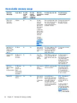
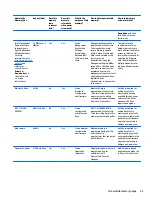
Nonvolatile memory usage

Nonvolatile
Memory Type

Amount (Size)

Does this
memory
store
customer
data?

Does this
memory
retain data
when power
is removed?

What is the
purpose of this
memory?

How is data input into this
memory?

How is this memory
write-protected?

HP Sure Start
flash (select
models only)

2 MBytes

No

Yes

Provides
protected
backup of
critical System
BIOS code, EC
firmware, and
critical PC
configuration
data for select
platforms that
support HP
Sure Start.

For more
information,
see 

Using HP

Sure Start
(select models
only)
on page 65

.

Data cannot be written to this
device via the host processor.
The content is managed
solely by the HP Sure Start
Embedded Controller.

This memory is protected
by the HP Sure Start
Embedded Controller.

Real Time Clock
(RTC) battery
backed-up CMOS
configuration
memory

256 Bytes

No

Yes

Stores system
date and time
and noncritical
data.

RTC battery backed-up CMOS
is programmed using the
Computer Setup (BIOS), or
changing the Microsoft
Windows date & time.

This memory is not write-
protected.

Controller (NIC)
EEPROM

64 KBytes (not
customer
accessible)

No

Yes

Stores NIC
configuration
and NIC
firmware.

NIC EEPROM is programmed
using a utility from the NIC
vendor that can be run from
DOS.

A utility is required to
write data to this
memory and is available
from the NIC vendor.
Writing data to this ROM
in an inappropriate
manner will render the
NIC non-functional.

DIMM Serial
Presence Detect
(SPD)
configuration data

256 Bytes per
memory
module, 128
Bytes
programmable
(not customer
accessible)

No

Yes

Stores memory
module
information.

DIMM SPD is programmed by
the memory vendor.

Data cannot be written to
this memory when the
module is installed in a
PC. The specific write-
protection method varies
by memory vendor.

System BIOS

4 MBytes to 5
MBytes

Yes

Yes

Stores system
BIOS code and
PC
configuration
data.

System BIOS code is
programmed at the factory.
Code is updated when the
system BIOS is updated.
Configuration data and
settings are input using the
Computer Setup (BIOS) or a
custom utility.

NOTE:

Writing data to

this ROM in an
inappropriate manner
can render the PC non-
functional.

A utility is required for
writing data to this
memory and is available
on the HP website; go to

http://www.hp.com/
support

, and select your

country. Select 

Drivers &

62

Chapter 11   Statement of memory volatility

Summary of Contents for HP 241 G1 Notebook PC

Page 1: ...HP 241 G1 Notebook PC Maintenance and Service Guide ...

Page 2: ...ary 2015 Document Part Number 799385 001 Product notice This guide describes features that are common to most models Some features may not be available on your computer Not all features are available in all editions of Windows 8 This computer may require upgraded and or separately purchased hardware drivers and or software to take full advantage of Windows 8 functionality See for http www microsof...

Page 3: ... another hard surface such as an adjoining optional printer or a soft surface such as pillows or rugs or clothing to block airflow Also do not allow the AC adapter to contact the skin or a soft surface such as pillows or rugs or clothing during operation The device and the AC adapter comply with the user accessible surface temperature limits defined by the International Standard for Safety of Info...

Page 4: ...iv Safety warning notice ...

Page 5: ...rage devices 15 Miscellaneous parts 15 Sequential part number listing 15 4 Removal and replacement preliminary requirements 17 Tools required 17 Service considerations 17 Plastic parts 17 Cables and connectors 18 Drive handling 18 Grounding guidelines 18 Electrostatic discharge damage 18 Packaging and transporting guidelines 20 Workstation guidelines 20 5 Removal and replacement procedures for Cus...

Page 6: ... BIOS version 48 Downloading a BIOS update 48 8 Using HP PC Hardware Diagnostics UEFI 50 Downloading HP PC Hardware Diagnostics UEFI to a USB device 50 9 Specifications 52 Computer specifications 52 35 6 cm 14 0 in display specifications 53 Hard drive specifications 54 10 Backing up restoring and recovering 55 Creating recovery media and backups 55 Creating HP Recovery media select models only 55 ...

Page 7: ...only 59 11 Statement of memory volatility 60 Nonvolatile memory usage 62 Questions and answers 64 Using HP Sure Start select models only 65 12 Power cord set requirements 66 Requirements for all countries 66 Requirements for specific countries and regions 66 13 Recycling 68 Index 69 vii ...
Page 8: ...viii ...

Page 9: ...33 MHz Single channel support Support for 2048 MB of system memory Models with on board memory Non accessible non upgradeable DDR3L 1066MHz 1 35V single channel support DDR3L 1600MHz downgrade to DDR3L 1066MHz Supports up to 2 GB max on board system memory Primary storage Support for 6 35 cm 2 5 in hard drives in 7 0 mm 28 in and 9 5 mm 37 in thickness Support for the following hard drives 500 GB ...

Page 10: ... resistant keyboard Touchpad configuration Multitouch gestures enabled Taps enabled as default Power requirements Support for a removable 6 cell 47 WHr 2 20 AHr Li ion battery Support for a removable 4 cell 41 WHr 2 80 AHr Li ion battery Support for a 65 W EM HP Smart adapter 4 5 mm Security Kensington Security Lock Operating system Preinstalled Microsoft Windows 8 1 Update PRO 64 Microsoft Window...

Page 11: ...m the list of applications 3 Internal microphone Record sound 4 WLAN antenna Send and receive wireless signals to communicate with wireless local area networks WLANs The antennas are not visible from the outside of the computer For optimal transmission keep the areas immediately around the antennas free from obstructions For wireless regulatory notices see the section of the Regulatory Safety and ...

Page 12: ... fully charged 3 External monitor port Connects an external VGA monitor or projector 4 Vent Enable airflow to cool internal components NOTE The computer fan starts up automatically to cool internal components and prevent overheating It is normal for the internal fan to cycle on and off during routine operation 5 RJ 45 network jack status lights Connects a network cable White The network is connect...

Page 13: ...lume before putting on headphones earbuds or a headset For additional safety information refer to the Regulatory Safety and Environmental Notices To access this document From the Start screen type support and then select the HP Support Assistant app or From the Windows desktop click the question mark icon in the notification area at the far right of the taskbar NOTE When a device is connected to t...

Page 14: ... pointer or activate items on the screen NOTE The TouchPad also supports edge swipe gestures 2 Left TouchPad button Functions like the left button on an external mouse 3 Right TouchPad button Functions like the right button on an external mouse 6 Chapter 2 External component identification ...

Page 15: ...keys to all capital letters 2 Mute light Amber Computer sound is off Off Computer sound is on 3 Wireless light On An integrated wireless device such as a wireless local area network WLAN device is on NOTE On some models the wireless light is amber when all wireless devices are off Top 7 ...

Page 16: ... the power button will result in the loss of unsaved information If the computer has stopped responding and Windows shutdown procedures are ineffective press and hold the power button down for at least 5 seconds to turn off the computer To learn more about your power settings see your power options From the Start screen type power select Power and sleep settings and then select Power and sleep fro...

Page 17: ...ecutes frequently used system functions when pressed in combination with the esc key or the spacebar 3 Windows key Returns you to the Start screen from an open app or the Windows desktop NOTE Pressing the Windows key again will return you to the previous screen 4 Action keys Execute frequently used system functions Top 9 ...

Page 18: ... Releases the battery 4 Vents 3 Enable airflow to cool internal components NOTE The computer fan starts up automatically to cool internal components and prevent overheating It is normal for the internal fan to cycle on and off during routine operation 5 Service door Provides access to the memory module slots 10 Chapter 2 External component identification ...

Page 19: ...ce label on your computer Component 1 Serial number 2 Product number 3 Warranty period 4 Model number select models only Microsoft Certificate of Authenticity label select models only prior to Windows 8 Contains the Windows Product Key You may need the Product Key to update or troubleshoot the operating system HP platforms with Windows 8 or Windows 8 x preinstalled do not have the physical label I...

Page 20: ...3 Illustrated parts catalog Computer major components 12 Chapter 3 Illustrated parts catalog ...

Page 21: ...7 Heat sink includes replacement thermal material 802480 001 8 RTC battery 718440 001 9 Fan includes cable 802479 001 10 WLAN module Qualcomm Atheros AR9565 802 11b g n 1 1 WiFi Bluetooth 4 0 Combo Adapter 675794 001 11 Audio USB board 802469 001 12 Hard drive does not include hard drive bracket or hard drive connector adapter NOTE The hard drive bracket rubber frame and cable are included in the ...

Page 22: ...e For use in models with a webcam 802483 001 For use in models without a webcam 805102 001 3 Webcam microphone module includes double sided adhesive 802486 001 4 Antenna Kit WLAN 802484 001 5 35 6 cm 14 0 in HD SVA display panel 802491 001 Display Hinge Kit includes 802485 001 6 Left and right display hinge brackets 7 Display enclosure 802482 001 14 Chapter 3 Illustrated parts catalog ...

Page 23: ...001 Hard Drive Hardware Kit includes 802471 001 2a Hard drive rubber frame 2b Hard drive brackets left and right 2c Hard drive connector cable Miscellaneous parts Component Spare part number 65 W HP Smart adapter non PFC EM 4 5 mm 714657 001 Power cord for use only in India 3 pin black 1 0 m 755530 D61 Rubber Kit 802487 001 Screw Kit 802475 001 Sequential part number listing CSR flag designations ...

Page 24: ... Screw Kit 802476 001 N Plastics Kit includes memory module compartment cover and optical drive bay space saver 802477 001 N Speaker Kit includes left and right speakers and cables 802479 001 N Fan includes cable 802480 001 N Heat sink includes replacement thermal material 802482 001 N Display enclosure 802483 001 N Display cable for use in models with a webcam 802484 001 N Antenna Kit includes le...

Page 25: ...ome of the considerations that you must keep in mind during disassembly and assembly procedures NOTE As you remove each subassembly from the computer place the subassembly and all accompanying screws away from the work area to prevent damage Plastic parts CAUTION Using excessive force during disassembly and reassembly can damage plastic parts Use care when handling the plastic parts Apply pressure...

Page 26: ... that have magnetic fields such as monitors or speakers Avoid exposing a drive to temperature extremes or liquids If a drive must be mailed place the drive in a bubble pack mailer or other suitable form of protective packaging and label the package FRAGILE Grounding guidelines Electrostatic discharge damage Electronic components are sensitive to electrostatic discharge ESD Circuitry design and str...

Page 27: ...Walking across carpet 35 000 V 15 000 V 7 500 V Walking across vinyl floor 12 000 V 5 000 V 3 000 V Motions of bench worker 6 000 V 800 V 400 V Removing DIPS from plastic tube 2 000 V 700 V 400 V Removing DIPS from vinyl tray 11 500 V 4 000 V 2 000 V Removing DIPS from Styrofoam 14 500 V 5 000 V 3 500 V Removing bubble pack from PCB 26 500 V 20 000 V 7 000 V Packing PCBs in foam lined box 21 000 V...

Page 28: ... proper materials are selected to avoid static charging When grounding is not possible use an ionizer to dissipate electric charges Workstation guidelines Follow these grounding workstation guidelines Cover the workstation with approved static shielding material Use a wrist strap connected to a properly grounded work surface and use properly grounded tools and equipment Use conductive field servic...

Page 29: ... resistance between the operator and ground To be effective the conductive must be worn in contact with the skin The following grounding equipment is recommended to prevent electrostatic damage Antistatic tape Antistatic smocks aprons and sleeve protectors Conductive bins and other assembly or soldering aids Nonconductive foam Conductive computerop workstations with ground cords of one megohm resi...

Page 30: ...ts for your computer go to http partsurfer hp com select your country or region and then follow the on screen instructions Component replacement procedures NOTE Please read and follow the procedures described here to access and replace Customer Self Repair parts successfully NOTE Details about your computer including model serial number product key and length of warranty are on the service tag at ...

Page 31: ...er WARNING To reduce potential safety issues use only the battery provided with the computer a replacement battery provided by HP or a compatible battery purchased from HP CAUTION Removing a battery that is the sole power source for the computer can cause loss of information To prevent loss of information save your work or shut down the computer through Windows before removing the battery Remove t...

Page 32: ...ct the power from the computer by unplugging the power cord from the computer 3 Disconnect all external devices from the computer 4 Remove the battery See Battery on page 23 Remove the memory cover 1 Loosen the Phillips PM2 5 4 5 captive screw 1 that secures the memory cover to the computer 2 Lift the rear edge of the memory cover 2 until it rests at an angle 3 Remove the memory cover 3 Reverse th...

Page 33: ...by unplugging the power cord from the computer 3 Disconnect all external devices from the computer 4 Remove the battery see Battery on page 23 5 Remove the memory cover see Memory cover on page 24 Remove the memory modules 1 Spread the retaining tabs 1 on each side of the memory module slot to release the memory module The memory module tilts up 2 Remove the memory module 2 by pulling the module a...

Page 34: ...or loosened when servicing the computer Make special note of each screw size and location during removal and replacement Base enclosure Description Spare part number Base enclosure includes TouchPad and TouchPad cable 802470 001 Before removing the base enclosure follow these steps 1 Turn off the computer If you are unsure whether the computer is off or in Hibernation turn the computer on and then...

Page 35: ...e 14 Phillips PM2 0 4 5 screws 2 that secure the top cover to the base enclosure 4 Lift the base enclosure from the computer Reverse this procedure to install the base enclosure Component replacement procedures 27 ...

Page 36: ...om the computer 3 Disconnect all external devices from the computer 4 Remove the battery see Battery on page 23 5 Remove the memory cover see Memory cover on page 24 6 Remove the bottom cover see Base enclosure on page 26 Remove the WLAN module 1 Disconnect the WLAN antenna cable 1 from the terminals on the WLAN module NOTE The WLAN antenna cable labeled 1 connects to the WLAN module Main terminal...

Page 37: ...le NOTE If the WLAN antenna cables are not connected to the terminals on the WLAN module protective sleeves should be installed on the antenna connectors as shown in the following illustration Reverse this procedure to install the WLAN module Component replacement procedures 29 ...

Page 38: ...ord from the computer 3 Disconnect all external devices from the computer 4 Remove the battery see Battery on page 23 5 Remove the memory cover see Memory cover on page 24 6 Remove the bottom cover see Base enclosure on page 26 Remove the hard drive 1 Disconnect the hard drive cable from the system board 1 2 Remove the hard drive 2 from the hard drive bay 3 If it is necessary to disassemble the ha...

Page 39: ...t and right sides of the hard drive bracket 2 from the hard drive d Remove the hard drive bracket 3 from the hard drive Reverse this procedure to reassemble and install the hard drive Component replacement procedures 31 ...

Page 40: ... Disconnect all external devices from the computer 4 Remove the battery see Battery on page 23 5 Remove the memory cover see Memory cover on page 24 6 Remove the bottom cover see Base enclosure on page 26 Remove the RTC battery 1 Turn the system board upside down with the front toward you 2 Use a plastic flat bladed tool to release the RTC battery from the socket on the system board Reverse this p...

Page 41: ...er by unplugging the power cord from the computer 3 Disconnect all external devices from the computer 4 Remove the battery see Battery on page 23 5 Remove the memory cover see Memory cover on page 24 6 Remove the bottom cover see Base enclosure on page 26 Remove the audio USB board 1 Disconnect the audio USB board cable from the system board 1 2 Remove the Philllips PM2 5 4 0 screw 2 that secures ...

Page 42: ...he power cord from the computer 3 Disconnect all external devices from the computer 4 Remove the battery see Battery on page 23 5 Remove the memory cover see Memory cover on page 24 6 Remove the bottom cover see Base enclosure on page 26 Remove the fan 1 Disconnect the fan cable from the system board 1 2 Loosen the two Phillips screws 2 that secure the fan to the system board 3 Remove the fan 3 Re...

Page 43: ...er on page 24 6 Remove the bottom cover see Base enclosure on page 26 Remove the heat sink 1 Turn the system board upside down with the front toward you 2 Following the 1 through 4 sequence stamped into the heat sink loosen the four Phillips captive screws 1 that secure the heat sink to the system board 3 Remove the heat sink 2 NOTE Due to the adhesive quality of the thermal material located betwe...

Page 44: ...stem 2 Disconnect the power from the computer by unplugging the power cord from the computer 3 Disconnect all external devices from the computer 4 Remove the battery see Battery on page 23 5 Remove the memory cover see Memory cover on page 24 6 Remove the bottom cover see Base enclosure on page 26 Remove the TouchPad button board 1 Turn the top cover upside down with the front toward you 2 Disconn...

Page 45: ... or in Hibernation turn the computer on and then shut it down through the operating system 2 Disconnect the power from the computer by unplugging the power cord from the computer 3 Disconnect all external devices from the computer 4 Remove the battery see Battery on page 23 5 Remove the memory cover see Memory cover on page 24 6 Remove the bottom cover see Base enclosure on page 26 NOTE When repla...

Page 46: ...ard cable 2 Remove the cable from atop the right speaker and then lift the speaker aside to gain access to the screw underneath 3 Remove the five Phillips PM2 5 3 0 screws that secure the system board to the base enclosure 1 4 Lift up on the left side of the system board 2 until it rests at an angle 38 Chapter 6 Removal and replacement procedures for Authorized Service Provider parts ...

Page 47: ...e computer on and then shut it down through the operating system 2 Disconnect the power from the computer by unplugging the power cord from the computer 3 Disconnect all external devices from the computer 4 Remove the battery see Battery on page 23 5 Remove the memory cover see Memory cover on page 24 6 Remove the bottom cover see Base enclosure on page 26 7 Remove the system board see System boar...

Page 48: ...2 Remove the speakers 2 Reverse this procedure to install the speakers 40 Chapter 6 Removal and replacement procedures for Authorized Service Provider parts ...

Page 49: ...es from the computer 4 Remove the battery see Battery on page 23 5 Remove the memory cover see Memory cover on page 24 6 Remove the bottom cover see Base enclosure on page 26 7 Remove the system board see System board on page 37 Remove the power connector cable 1 Remove the Phillips broadhead PM2 5 3 0 screw 1 that secures the display hinge and power connector 2 Rotate the display hinge upward to ...

Page 50: ...e Battery on page 23 5 Remove the memory cover see Memory cover on page 24 6 Remove the bottom cover see Base enclosure on page 26 7 Remove the system board see System board on page 37 Remove the display assembly 1 Position the computer upside down with the display hanging off the edge of the table 2 Remove the Phillips PM2 5 4 0 screw 1 that secures the right display hinge to the computer 3 Remov...

Page 51: ...m the display enclosure d Remove the display bezel 4 The display bezel is available using spare part number 805099 001 for models with a webcam and 805100 001 for models without a webcam 6 If it is necessary to replace the webcam microphone module a Detach the webcam microphone module 1 from the display enclosure The webcam microphone module is attached to the display enclosure with double sided a...

Page 52: ...screws that secure the display panel to the display enclosure CAUTION Before turning the display panel upside down make sure the work surface is clear of tools screws and any other foreign objects Failure to follow this caution can result in damage to the display panel b Lift the top edge of the display panel 1 and swing it up and forward until it rests upside down in front of the display enclosur...

Page 53: ...nel cable 3 from the display panel e Remove the display panel The display panel is available using spare part number 802491 001 8 If it is necessary to replace the display hinges a Remove the four Phillips PM2 5 3 25 broadhead screws 1 that secure the display hinges to the display enclosure Component replacement procedures 45 ...

Page 54: ...nel built into the top right and bottom edges of the display enclosure b Remove the display cable from the display enclosure 2 The display cable is available using spare part number 802483 001 for models with a webcam and 805102 001 for models with out a webcam 10 If it is necessary to replace the WLAN antenna cables and transceivers 46 Chapter 6 Removal and replacement procedures for Authorized S...

Page 55: ...r 2 from the display enclosure The WLAN antenna transceiver is attached to the display enclosure with double sided adhesive c Remove the WLAN antenna cable and transceiver The WLAN antenna cable and transceiver is included in the Antenna Kit spare part number 802484 001 Reverse this procedure to reassemble install the display assembly Component replacement procedures 47 ...

Page 56: ...d BIOS version information also known as ROM date and System BIOS can be revealed from the Start screen by typing support selecting the HP Support Assistant app and then selecting System Information or by using Setup Utility BIOS 1 Start Setup Utility BIOS see Starting Setup Utility BIOS on page 48 2 Select Main and then make note of your BIOS version 3 Select Exit select Exit Discarding Changes a...

Page 57: ...te of the path to the location on your hard drive where the BIOS update is downloaded You will need to access this path when you are ready to install the update BIOS installation procedures vary Follow any instructions that appear on the screen after the download is complete If no instructions appear follow these steps 1 From the Start screen type file and then select File Explorer or From the Win...

Page 58: ...diagnostic tool opens use the keyboard arrow keys to select the type of diagnostic test you want to run and then follow the on screen instructions NOTE If you need to stop a diagnostic test press or tap esc Downloading HP PC Hardware Diagnostics UEFI to a USB device NOTE Instructions for downloading HP PC Hardware Diagnostics UEFI are provided in English only There are two options to download HP P...

Page 59: ...computer model and then select your operating system 5 In the Diagnostic section click HP UEFI Support Environment or Click Download and then select Run Downloading HP PC Hardware Diagnostics UEFI to a USB device 51 ...

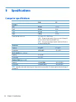
Page 60: ...mputer operating voltage and current can be found on the system regulatory label Temperature Operating 5 C to 35 C 41 F to 95 F Nonoperating 20 C to 60 C 4 F to 140 F Relative humidity non condensing Operating 10 to 90 Nonoperating 5 to 95 Maximum altitude unpressurized Operating 15 m to 3 048 m 50 ft to 10 000 ft Nonoperating 15 m to 12 192 m 50 ft to 40 000 ft NOTE Applicable product safety stan...

Page 61: ...14 06 in Number of colors up to 16 8 million Contrast ratio 200 1 typical Brightness 200 nits typical Pixel resolution Pitch 0 197 0 197 mm Format HD SVA 1366 x 768 Configuration RGB vertical stripe Backlight LED Character display 80 25 Viewing angle 65 horizontal 50 vertical typical 35 6 cm 14 0 in display specifications 53 ...

Page 62: ...security Seek times typical read including setting Single track 1 5 ms 1 5 ms Average read write 11 13 ms 11 13 ms Maximum 22 ms 22 ms Logical blocks 976 773 168 488 386 584 Disk rotational speed 5400 rpm 5400 rpm Operating temperature 1 GB 1 billion bytes when referring to hard drive storage capacity Actual accessible capacity is less NOTE Certain restrictions and exclusions apply Contact technic...

Page 63: ...g recovery media see Creating HP Recovery media select models only on page 55 For information on the recovery options that are available using the recovery media see Recovering using HP Recovery Manager on page 57 Use Windows tools to create system restore points and create backups of personal information For more information see Using Windows tools on page 56 NOTE If storage is 32 GB or less Micr...

Page 64: ...onnected to a USB port on an external device such as a USB hub Be sure that the computer is connected to AC power before you begin creating the recovery media The creation process can take an hour or more Do not interrupt the creation process If necessary you can exit the program before you have finished creating all of the recovery DVDs HP Recovery Manager will finish burning the current DVD The ...

Page 65: ...ng HP Recovery Manager on page 57 If you have not already created recovery media see Creating HP Recovery media select models only on page 55 On select models if you want to recover the computer s original factory partition and content or if you have replaced the hard drive you can use the Factory Reset option of HP Recovery media For more information see Recovering using HP Recovery Manager on pa...

Page 66: ...to its original factory state by deleting all information from the hard drive and re creating the partitions Then it reinstalls the operating system and the software that was installed at the factory The HP Recovery partition select models only allows System Recovery and Minimized Image Recovery select models only Using the HP Recovery partition select models only The HP Recovery partition allows ...

Page 67: ...elect models only HP Recovery Manager software allows you to remove the HP Recovery partition to free up hard drive space IMPORTANT After you remove the HP Recovery partition you can no longer use the Windows Refresh option or the Windows option to remove everything and reinstall Windows In addition you will not be able to perform System Recovery or Minimized Image Recovery from the HP Recovery pa...

Page 68: ...ecommended a Turn on or restart the computer and then press esc while the Press the ESC key for Startup Menu message is displayed at the bottom of the screen NOTE If the system has a BIOS administrator password enter the password at the prompt b Select Main select Restore Defaults and then select Yes to load defaults c Select the Security menu select Restore Security Level Defaults and then select...

Page 69: ...the bottom of the screen b Select the Security menu and scroll down to the Utilities menu c Select Hard Drive Tools d Under Utilities select Secure Erase select the hard drive storing the data you want to clear and then follow the on screen instructions to continue or Clear the contents of the drive by using the following Disk Sanitizer command steps IMPORTANT If you clear data using Disk Sanitize...

Page 70: ...t customer accessible No Yes Stores NIC configuration and NIC firmware NIC EEPROM is programmed using a utility from the NIC vendor that can be run from DOS A utility is required to write data to this memory and is available from the NIC vendor Writing data to this ROM in an inappropriate manner will render the NIC non functional DIMM Serial Presence Detect SPD configuration data 256 Bytes per mem...

Page 71: ...mware updates digitally signed by Intel can be applied using this utility Bluetooth flash 2 Mbit No Yes Stores Bluetooth configuration and firmware Bluetooth flash is programmed at the factory Tools for writing data to this memory are not publicly available but can be obtained from the silicon vendor A utility is required for writing data to this memory and is made available through newer versions...

Page 72: ...m diagnostics The UEFI BIOS provides functionality beyond that of the legacy BIOS In addition the UEFI BIOS works to initialize the computer s hardware before loading and executing the OS the run time environment allows the loading and execution of software programs from storage devices to provide more functionality such as advanced hardware diagnostics with the ability to display more detailed sy...

Page 73: ... Turn on or restart the computer and then press esc while the Press the ESC key for Startup Menu message is displayed at the bottom of the screen b Select the Security menu select Secure Boot Configuration and then follow the on screen instructions c At the Secure Boot Configuration window select Secure Boot select Clear Secure Boot Keys and then follow the on screen instructions to continue Using...

Page 74: ...roved by an acceptable accredited agency responsible for evaluation in the country or region where the power cord set will be used The power cord sets must have a minimum current capacity of 10 amps and a nominal voltage rating of 125 or 250 V AC as required by the power system of each country or region The appliance coupler must meet the mechanical configuration of an EN 60 320 IEC 320 Standard S...

Page 75: ...ord and wall plug must bear a T mark and registration number in accordance with the Japanese Dentori Law The flexible cord must be Type VCT or VCTF 3 conductor 1 00 mm conductor size The wall plug must be a two pole grounding type with a Japanese Industrial Standard C8303 7 A 125 V configuration 4 The flexible cord must be Type RVV 3 conductor 0 75 mm conductor size Power cord set fittings applian...

Page 76: ...in general household waste Follow the local laws and regulations in your area for battery disposal HP encourages customers to recycle used electronic hardware HP original print cartridges and rechargeable batteries For more information about recycling programs see the HP Web site at http www hp com recycle 68 Chapter 13 Recycling ...

Page 77: ... D display specifications 53 display assembly removal 42 spare part numbers 14 display bezel removal 42 spare part number 14 16 43 display cable removal 46 spare part number 16 display enclosure spare part number 14 16 Display Hinge Kit spare part number 14 16 46 display panel product description 1 removal 44 spare part number 14 16 45 display panel cable spare part number 14 46 drives preventing ...

Page 78: ...ifying 7 N network jack identifying 4 nonvolatile memory 60 O operating system product description 2 original system recovery 57 P packaging guidelines 20 plastic parts service considerations 17 Plastics Kit spare part number 13 16 pointing device product description 2 ports external monitor 4 product description 2 USB 2 0 5 USB 3 0 4 power button identifying 8 power connector cable removal 41 spa...

Page 79: ...ery 56 system board removal 37 spare part numbers 13 16 37 system memory removing personal data from volatile 60 system recovery 57 system restore point creating 56 system restore point creating 55 T tools required 17 top cover spare part number 13 TouchPad buttons 6 TouchPad button board removal 36 spare part number 13 36 touchpad button board spare part number 16 TouchPad zone identifying 6 tran...

Reviews: