background image

1.

Start the device using the power button.

2.

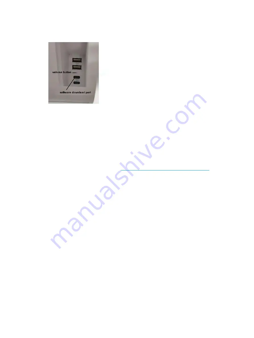
Press and release the volume button, located between the USB ports on the back of the device.

3.

Use the volume button to navigate to Fastboot, and then use the power button to select.

Downloading the Android Bootloader driver

1.

Using the first (top) USB Type-C port, connect the device to a Windows computer.

2.

Open Windows Device Manager.

3.

Find the Android device. It may be listed under Other devices.

Confirm that Android Bootloader is displayed under the Android device. If Android Bootloader is not 
displayed:

a.

Download Android Bootloader from 

https://developer.android.com/studio/run/win-usb

.

b.

In Device Manager, right click the Android device. It may be labeled ‘Android’.

c.

Select Update Driver.

d.

Select Browse my computer for driver software.

e.

Select Let me pick from a list.

f.

Select Android Device, and then click Next.

g.

Select Have Disk.

h.

Browse to the downloaded ABI files, and then select OK.

4.

Unzip and open the Android OTA image files.

5.

Open flash-all.bat.

After the flash has completed, the device automatically starts the installed operating system.

12

Chapter 2   Using and updating the computer

Summary of Contents for Engage One Prime

Page 1: ...Maintenance and Service Guide HP Engage One Prime ...

Page 2: ...companying such products and services Nothing herein should be construed as constituting an additional warranty HP shall not be liable for technical or editorial errors or omissions contained herein First Edition February 2019 Document Part Number L45321 001 Product notice This user guide describes features that are common to most models Some features may not be available on your computer Software...

Page 3: ...he computer 9 Turning on the computer 9 Turning off the computer 9 Installing HP updates 9 Updating the firmware 9 Performing a soft reset 9 Computer power button light behavior 9 Hub power light behavior 10 Over the air OTA update 10 Preparing the USB flash drive 10 Performing the OTA update from the Additional System Updates menu 10 Performing the OTA update from Recovery 11 Operating system rec...

Page 4: ...ersonal grounding methods and equipment 16 Grounding the work area 16 Recommended materials and equipment 17 Appendix A Power cord set requirements 18 General requirements 18 Japanese power cord requirements 18 Country specific requirements 19 Appendix B Statement of memory volatility 20 Nonvolatile memory usage 21 Appendix C Specifications 22 Computer specifications 22 Main display specifications...

Page 5: ...e with 1 8 GHz 2 GB memory 16 GB eMMC models Two USB Type A and two USB Type C ports Near Field Communications NFC Integrated magnetic stripe reader MSR Integrated Wi Fi Integrated Bluetooth Front and rear cameras rear camera primarily used to rear barcodes Optional customer facing display Expanded connectivity with optional hub Optional handheld barcode scanner Optional iButton Optional standalon...

Page 6: ...mera light 6 Power button 3 Magnetic stripe reader MSR light 7 Power button light 4 Front facing camera Rear components Table 1 2 Rear components Rear components 1 Security cable slot 4 USB Type C ports 2 2 USB Type A ports 2 5 Customer facing display optional 3 Volume button 2 Chapter 1 Product overview ...

Page 7: ...mponents 1 Power connector 7 USB Type C port 2 USB Type C powered port 8 RJ 45 network jack 3 Cash drawer jack 9 Security cable slot 4 Powered serial ports 10 Wall mount keyholes 5 Powered USB 12 V port 11 Power light 6 USB ports 4 Optional hub components 3 ...

Page 8: ... 0 volts 5 volts 12 volts To change the voltage setting for each powered serial port 1 In the software included with the product select Settings 2 Select Connected devices and then select Powered Serial Port Voltage 3 Select the appropriate voltage for the connected device IMPORTANT To reduce the risk of damage to a connected device make sure that you select the correct serial port voltage Mountin...

Page 9: ...er 3 NOTE If the computer is connected to the optional hub you can connect a USB Type C cable to the hub s USB Type C powered port instead of using the AC adapter to power the computer Connecting power to the hub To connect an AC adapter to the hub connect one end of the power cord to the AC adapter 1 and the other end to a grounded AC outlet 2 and then connect the AC adapter to the power connecto...

Page 10: ...an AC adapter when connected to the USB Type C powered port on the hub Locating the computer power button The power button is located on the bottom right edge of the bezel NOTE The power button light is white when the computer is on The power button light is off when the computer is off The power button light blinks when the computer is in the Sleep state 6 Chapter 1 Product overview ...

Page 11: ...e position of the computer The computer can be stabilized at various angles to adjust for glare and counter height Computer serial number location Each computer has a unique serial number and a product ID number that are located on the exterior of the unit Keep these numbers available for use when contacting support for assistance Adjusting the tilt 7 ...

Page 12: ...e when contacting support for assistance Contacting support To resolve a hardware or software problem go to http www hp com support Use this site to get more information about your product including links to discussion forums and instructions on troubleshooting You can also find information about how to contact HP and open a support case 8 Chapter 1 Product overview ...

Page 13: ...Select the available update and follow on screen instructions Performing a soft reset Press and hold the power button for about 10 seconds to reset the computer TIP The only function of the RTC battery is to keep the current time Android devices do not include a BIOS or CMOS Computer power button light behavior The computer power button light functions as follows On S0 Computer is on Off S5 Comput...

Page 14: ...computer power button light location see Bezel components on page 2 For more information about the hub power light location see Optional hub components on page 3 Over the air OTA update Preparing the USB flash drive Performing an OTA update requires a 2 GB or larger USB flash drive You must format the drive using the FAT32 file system To prepare the USB flash drive 1 Insert the USB flash drive con...

Page 15: ...lume button press the power button to turn the device on 2 Move the cursor to Apply update from SD Card and then press the power button to select 3 Select the OTA update package and then press the power button to start the update After the update has completed the Android Recovery screen displays 4 Select Reboot system now to restart the computer 5 Go to the About device menu and check the build n...

Page 16: ...ader is displayed under the Android device If Android Bootloader is not displayed a Download Android Bootloader from https developer android com studio run win usb b In Device Manager right click the Android device It may be labeled Android c Select Update Driver d Select Browse my computer for driver software e Select Let me pick from a list f Select Android Device and then click Next g Select Ha...

Page 17: ...soft damp cloth as necessary Using cleaning products may discolor or damage the finish NOTE For more information on your retail system care and maintenance go to http www hp com support Then type Retail Point of Sales Systems Routine Care and Maintenance and click Search all support Touch screen maintenance Keep your touch screen clean The touch screen requires very little maintenance HP recommend...

Page 18: ...any debris that has accumulated in and around these ports Updating drivers and firmware HP recommends that you regularly download and install the latest drivers and firmware updates to help enhance system performance resolve known issues and avoid replacing parts unnecessarily To download and install the latest drivers and updates for your specific Retail Point of Sale model go to http www hp com ...

Page 19: ...ctronic components as little as possible If you remove a component place it in an electrostatic safe container Generating static electricity Note the following Different activities generate different amounts of static electricity Static electricity increases as humidity decreases Table 3 1 Static electricity occurrence based on activity and humidity Relative humidity Event 55 40 10 Walking across ...

Page 20: ... compatible with most types of shoes or boots On conductive floors or dissipative floor mats use them on both feet with a maximum of one megohm 10 resistance between the operator and ground Table 3 2 Static shielding protection levels Static shielding protection levels Method Voltage Antistatic plastic Carbon loaded plastic Metallized laminate 1 500 7 500 15 000 Grounding the work area To prevent ...

Page 21: ...ive tabletop workstations with ground cord of one megohm 10 resistance Static dissipative table or floor mats with hard tie to ground Field service kits Static awareness labels Wrist straps and footwear straps providing one megohm 10 resistance Material handling packages Conductive plastic bags Conductive plastic tubes Conductive tote boxes Opaque shielding bags Transparent metallized shielding ba...

Page 22: ...ncy responsible for evaluation in the country where the power cord set will be installed 2 The power cord set must have a minimum current capacity of 10A 7A Japan only and a nominal voltage rating of 125 or 250 volts AC as required by each country s power system 3 The diameter of the wire must be a minimum of 0 75 mm2 or 18AWG and the length of the cord must be between 1 8 m 6 feet and 3 6 m 12 fe...

Page 23: ... conductor size Power cord set fittings appliance coupler and wall plug must bear the certification mark of the agency responsible for evaluation in the country where it will be used 2 The flexible cord must be Type SVT or equivalent No 18 AWG 3 conductor The wall plug must be a two pole grounding type with a NEMA 5 15P 15A 125V or NEMA 6 15P 15A 250V configuration 3 Appliance coupler flexible cor...

Page 24: ...configuration Intel based and AMD based system boards contain nonvolatile memory subcomponents as originally shipped from HP assuming that no subsequent modifications have been made to the system and assuming that no applications features or functionality have been added to or installed on the system Following system shutdown and removal of all power sources from an HP Business computer system per...

Page 25: ...pecific write protection method varies by memory vendor Bluetooth flash select products only 2 Mb No Yes Stores Bluetooth configuration and firmware Bluetooth flash is programmed at the factory Tools for writing data to this memory are not publicly available but can be obtained from the silicon vendor A utility must be used for writing data to this memory and is made available through newer versio...

Page 26: ...90 V 265 VAC Rated line frequency 50 60 HZ Operating line frequency range 47 63 HZ Rated input current 1 4A RMS 90 VAC max load 2 2A RMS 90 VAC max load Magnetic Stripe Reader Integrated MSR reader triple track head ISO 7811 7812 7813 Compliant encryption capable Front Camera Integrated front camera 5M FF Barcode Reader back camera Integrated back camera 5M FF with flash LED Acoustic functions 1 m...

Page 27: ...62K Brightness Typical 220 nits2 Contrast ratio Typical 700 12 Pixel pitch 161 μm 161 μm Viewing angle Horizontal 85 Vertical 85 Response rate 30 ms Backlight LED Surface treatment Anti glare 1 All specifications represent the typical specifications provided by HP s component manufacturers actual performance may vary either higher or lower 2 Nits is the measure of the typical brightness of the pan...

Page 28: ... ratio 16 9 Maximum color 16 7M Brightness Typical 420 nits2 Contrast ratio Minimum 100K 1 Pixel pitch 63 25 μm 63 25 μm Viewing angle All view Response rate 1 ms 1 All specifications represent the typical specifications provided by HP s component manufacturers actual performance may vary either higher or lower 2 Nits is the measure of the typical brightness of the panel as specified prior to anti...

Page 29: ... 20 volatile 20 MSR maintenance 13 N nonvolatile memory 20 O operating guidelines 13 operating system recovery 11 OTA update from Additional System Updates menu 10 OTA update from Recovery 11 P performing a soft reset 9 ports cleaning 14 power button 6 power cord set requirements country specific 19 powering off the computer 9 powering on the computer 9 printer cleaning 14 R recovery 11 removing p...

Reviews: