5.
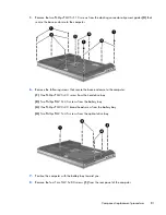
Remove the two Phillips PM2.5×11.0 screws from the docking connector alignment guides
(3)
that
secure the base enclosure to the computer.
6.
Remove the following screws that secure the base enclosure to the computer:
(1)
One Phillips PM2.0×3.0 screw from the hard drive bay
(2)
Two Phillips PM2.0×3.0 screws from the battery bay
(3)
One Phillips PM2.0×4.0 broad head screw from the battery bay
(4)
Two Phillips PM2.5×4.5 screws from the optical drive bay
7.
Position the computer with the battery bay toward you.
8.
Remove the four Torx TM2.5×8.0 screws
(1)
from the rear panel of the computer.
Component replacement procedures
81


