background image

10 


3


Illustrated parts catalog 

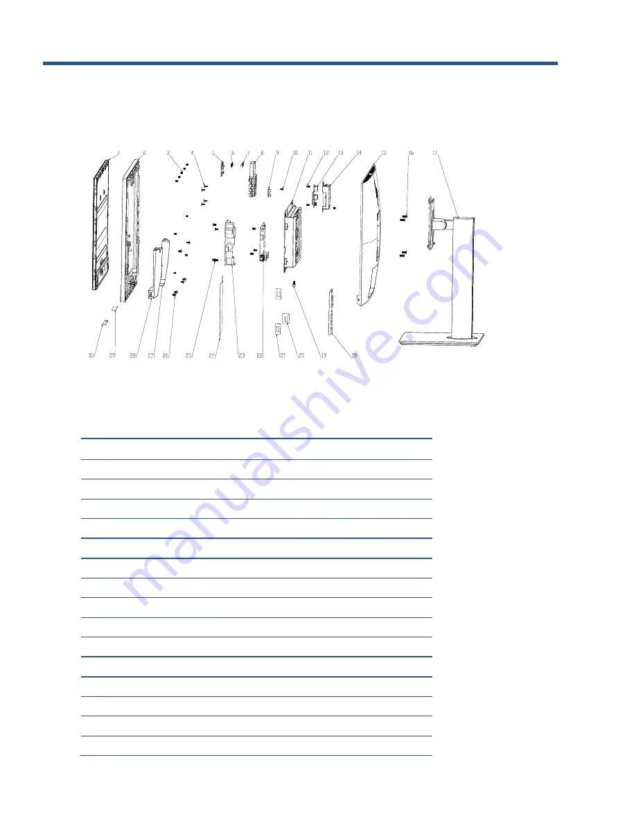
To identify the monitor major components, use this illustration and table. 


Mechanical explosion


Item 

Description 

Qty 

PANEL 

ASSY, BEZEL, ASTROID, WBP, BOE-EC, E243m 

SCREW, I, CROSS, M3*4 ZN-CC 

10 

SCREW, I, CROSS, T3*8, Zn 

5* 

ASSY, POP-UP MODULE, NEW, E243m 

Webcam 

7* 

ASSY, POP-UP MODULE, NEW, E243m 

8* 

ASSY, POP-UP MODULE, NEW, E243m 

Webcam Control Board 

10 

SCREW, I, CROSS T, T3*6 ZN CC 

11 

ASSY, CHASSIS, E243m, LP24QA 

12 

SCREW, P, CROSS M3*6, ZN-CC 

13 

Side USB Board 

14 

ASSY, USB COVER, E243m, LP24QA 

15 

ASSY, BUCKET, JACK BLACK, E243m, LP24QA 

16 

SCREW, I, CROSS, M4*10, BLK-NL 

Summary of Contents for E243M

Page 1: ...Maintenance and Service Guide E243m model SUMMARY This guide provides information about spare parts removal and replacement of parts diagnostic tests problem troubleshooting and more ...

Page 2: ...d States and other countries The information contained herein is subject to change without notice The only warranties for HP products and services are set forth in the express warranty statements accompanying such products and services Nothing herein should be construed as constituting an additional warranty HP shall not be liable for technical or editorial errors or omissions contained herein Fir...

Page 3: ... Front components 5 Rear components 7 Locating the serial number and product number 8 3 Illustrated parts catalog 10 How to order parts 12 4 Removal and replacement procedures 14 Preparation for disassembly 14 RC 14 Power board 19 Connector repair 21 Audio connector CN50 22 HDMI connector CN301 22 VGA connector CN201 23 USB upstream connector CN602 24 USB connector P101 P102 24 Headphone connector...

Page 4: ......

Page 5: ...opening the product s cabinet Modules containing electrical components are sensitive to electrostatic discharge ESD Follow ESD safety procedures while handling these parts Some products contain more than one battery Do not disassemble or expose a battery to high temperatures such as throwing into fire or the battery may explode Refer to government requirements for battery recycling or disposal Thi...

Page 6: ...tance in Electrical and Electronic Equipment Directive is a legal requirement by the EU European Union for the global electronics industry sold in the EU and other countries Any electrical and electronics products launched in the market after June 2006 should meet this RoHS requirement Products launched in the market before June 2006 are not required to be compliant with RoHS parts If the original...

Page 7: ...el and height adjustment capabilities Removable stand for flexible monitor panel mounting solutions DisplayPort and VGA video inputs cables provided One HDMI High Definition Multimedia Interface video input cable not provided USB 3 0 hub with one upstream port connects to the computer and two downstream ports connect to USB devices USB BM to AM cable provided to connect the monitor s USB hub to th...

Page 8: ...tion NOTE For safety and regulatory information refer to the Product Notices provided in your documentation kit To access the latest user guides or manuals for your product go to http www hp com support and follow the instructions to find your product Then select Manuals ...

Page 9: ...e phone Green light and red light blink when there is an incoming call 7 Mute microphone button Press to mute or activate the camera microphone Illuminates amber when microphone is muted 8 Mute speaker button Press to mute or activate the speakers Illuminates amber when speakers are muted 9 Reject Hang up button Press to decline or end a call Green light and red light blink when there is an incomi...

Page 10: ...guretheFunctionbuttonsintheOSDmenuto quickly select the most commonly used operations See Assigning the function buttonsonpage20formoreinformation 12 Power button Pressthebuttontoturnthemonitoronoroff Whenthemonitorison the powerlightabovethepowerbuttonison ...

Page 11: ...njury reducethe volumebeforeusingheadphones earbuds oraheadset For additionalsafetyinformation seetheProduct Notices provided ontheopticaldisc ifoneisincludedwithyourproduct NOTE Whenadeviceisconnectedtotheheadphonejack the monitor speakersaredisabled 3 Power connector Connects the power cord 4 DisplayPort port Connects the DisplayPort cable to the source device 5 HDMI port Connects the HDMI cable...

Page 12: ...f the monitor The serial number and product number are located on a Safety label You may need these numbers when contacting HP about the monitor model Label Location For worldwide models except India Barcode label Barcode label for Worldwide region Spec label Spec label for Worldwide region India Barcode Label ...

Page 13: ...9 Barcode label for India region ...

Page 14: ...W I CROSS M3 4 ZN CC 10 4 SCREW I CROSS T3 8 Zn 4 5 ASSY POP UP MODULE NEW E243m 1 6 Webcam 1 7 ASSY POP UP MODULE NEW E243m 1 8 ASSY POP UP MODULE NEW E243m 1 9 Webcam Control Board 1 10 SCREW I CROSS T T3 6 ZN CC 6 11 ASSY CHASSIS E243m LP24QA 1 12 SCREW P CROSS M3 6 ZN CC 8 13 Side USB Board 1 14 ASSY USB COVER E243m LP24QA 1 15 ASSY BUCKET JACK BLACK E243m LP24QA 1 16 SCREW I CROSS M4 10 BLK N...

Page 15: ...x11 8 Ni FOR D SUB DVI C1018 2 20 MYLAR CHASSIS MAIN E233 SIDE 1 1 21 MYLAR CHASSIS MAIN E233 SIDE 2 2 22 IF BD 1 23 PWR BD 1 24 MYLAR FOR PI FRONT E243m LP24QA 1 25 SCREW PW CROSS M4X9 Zn CC 1 26 SCREW P CROSSW WAS T3X6 BLACK ZN 6 27 SPK L 1 28 SPK R 1 29 LYNC keypad 1 30 PWR OSD Keypad 1 ...

Page 16: ...itors and connectors are available for purchase from the following EU distributors Farnell Farnell UK Electronic Components Distributor RS Component Capacitors RS Components rs online com Digi Key Component Digi Key Electronic United Kingdom Capacitors by distributor Component description Location Component distributor Distributor part number Capacitor 470 µF 10 16 8K C864 and C865 Farnell RS EEUF...

Page 17: ...ed to meet functionality regulatory and safety requirements if it is not an exact match You can purchase cables from the HP part store at https partsurfer hp com Search aspx NOTE HP continually improves and changes product parts For complete and current information about supported parts for your computer go to http partsurfer com select your country or region and then follow the on screen instruct...

Page 18: ...r of this guide 2 Clean the room for disassembly 3 Identify the disassembly area 4 Check the position that the monitors are to be placed along with the number of monitors Prepare the area for material flow according to the disassembly layout 5 Be sure to have the following equipment and materials Press fixture Working table Screwdriver Knife Gloves Cleaning cloth ESD protection Scraper bar in the ...

Page 19: ...e frame and rear case and then rotate The hook opens Repeat the steps Be careful with four corners DO NOT move away rear case immediately Separate rear cover and middle frame step Separate rear cover and middle frame step 3 Hang up rear case disconnect the webcam control cable and then take away rear case Webcam cable separate step ...

Page 20: ...ver pull it rightward and reverse then disconnect the cable 6 Peel the foils off disconnect the backlight cable and LVDS cable Take out the OSD keypad and LYNC keypad cable and materials separate step 7 Take away the metal chassis unscrew middle frame from panel Separate middle frame and panel Speaker separate step USB side chassis separate step ...

Page 21: ...Take off screw from USB side board 11 Unscrew push push webcam module from rear case Take off screw from rear cover 12 Peel off gasket conductive fabric foil and tape 13 Reverse the module PUSH it to OPEN and unscrew webcam control board Disconnect webcam control board and pass the cable through the module PCBA and Chassis separate step Take out all cables from PCBA Separate webcam module step ...

Page 22: ...k three flat screws peel off conductive fabric insert the scraper bar and separate the two plastic parts 16 Unhook the webcam and disconnect the cable Be noticed that the webcam is sticked with the plastic sheet too Separate webcam board module step Separate webcam module step Separate webcam module step Separate webcam module step ...

Page 23: ...epare the monitor for disassembly See Preparation for disassembly on page 14 Remove the power board 1 The HP E243m power board connector position is as follows Power Board location showing of connector CN4 Foxconn P N 3406BA900 39U H CN851 Foxconn P N 35104C700 39U H 2 Locate the part number location on the board ...

Page 24: ...20 Part number location of power board 3 Remove the backlight cable and main board Remove the backlight cable and main board ...

Page 25: ...nectors are on the main board board part number 790NQ1300 H01 and USB side board board part number 790NQ0300 H0 The connectors identifiers are as follows Connector Location HDMI CN301 DisplayPort CN401 Audio in CN502 USB upstream CN602 Connector location showing of main board Connector Location USB P101 P102 Headphone CN101 ...

Page 26: ...e a hot air gun to melt the solder on the pins Pin solder with soldering iron and absorber You can gently push down with the soldering iron once everything is molten to move the CN502 out of the through holes Audio connector repairing 2 Lift the CN502 connector from the PCB 3 Place the new component on the PCB Be sure that it matches the PCB footprint 4 Solder the new component HDMI connector CN30...

Page 27: ...CB 4 Place the new component on the PCB Be sure that it matches the PCB footprint 5 Solder the new component VGA connector CN201 Repair the DP connector 1 Use a hot air gun to melt the solder on the pins Pin solder with soldering iron and absorber You can gently push down with the soldering iron once everything is molten to move the CN201 out of the through holes VGA D Sub connector repairing 2 Li...

Page 28: ...nector repairing 2 Lift the CN602 connector from the PCB 3 Place the new component on the PCB Be sure that it matches the PCB footprint 4 Solder the new component USB connector P101 P102 Repair the USB connector 1 Use a hot air gun to melt the solder on the pins Pin solder with soldering iron and absorber You can gently push down with the soldering iron once everything is molten to move the P101 P...

Page 29: ...on Tool used HDMI test Confirm whether image displays and sound plays correctly on the monitor Computer or DVD player DP test Confirm whether image displays and sound plays correctly on the monitor Computer or DVD player Audio test Change volume and balance to confirm whether volume is smooth and loud enough Speaker Table 4 1 Function test Test item Operating description Tool used HDMI test Confir...

Page 30: ...ess scale as needed Check Video Cable is displayed on screen Monitor video cable is disconnected Connect the appropriate video signal cable between the computer and monitor Be sure that the computer power is off while you connect the video cable Input Signal Out of Range is displayed on screen Video resolution and or refresh rate are set higher than what the monitor supports Change the settings to...

Page 31: ...ard removal 15 power button location 5 power connector location 6 power light location 5 precautions 1 preparation for disassembly 12 RC removal 12 rear components 6 removal power board 15 RC 12 xxxx 20 removal and replacement procedures 12 returning to customer 2 RoHS 2002 95 EC requirements 2 safety information 1 serial number location 7 service information 1 spare parts 9 support and troublesho...

Page 32: ...28 ...

Page 33: ...29 ...

Reviews: