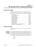
SCPI Command Format
SCPI commands perform functions like setting outputs, querying instrument states,
or retrieving data. The command structure is a hierarchical structure that usually
consists of a top level (or root) command, one or more lower level commands, and
their parameters. The following example shows part of a typical subsystem:
SOURce
n
:
FUNCtion:
MODE <CURRent | VOLTage>
SOURce
n: is the root command (where n is replaced by the channel number in the
range of 1 to 16),
FUNCtion:
is a second level command,
MODE
is a third level
command, and
<CURRent | VOLTage>
is an input parameter.
Command
Separator
A colon (:) always separates one command from the next lower level command.
This is illustrated as follows:
SOURce
n
:FUNCtion:MODE VOLT
Colons separate the root command from the second level (
SOURce
n
:FUNCtion
) and
the second from third level (
FUNCtion:MODE
), and so forth.
Abbreviated and
Short Commands
The command syntax shows most commands as a mix of upper and lower case
letters. The upper case letters indicate an abbreviated spelling for the command.
For shorter program lines, send only the abbreviated form. For better program
readability use the entire command. The instrument will accept either the
abbreviated form or the entire command.
For example, if the command reference syntax shows the command
TRIGger
, then
TRIG
and
TRIGGER
are both acceptable forms. Other forms of
TRIGger
, such as
TRIGG
or
TRIGGE
will generate an error.
The instrument does not distinguish between upper case and lower case characters.
Therefore
TRIGGER
,
trigger
, and
TrigGeR
are all acceptable.
Command keywords can be entered in their full form, as shown above, or can be
entered in their short form. In this manual, the entry required in short form
commands is always capitalized. The short form is generally used for examples in
this manual.
59 HP E1418A SCPI Command Reference
Chapter 3
Summary of Contents for E1418A
Page 6: ...Notes 6 Contents HP E1418A 8 16 Channel D A Converter Module ...
Page 10: ...Notes 10 HP E1418A User s Manual ...
Page 12: ...12 HP E1418A User s Manual ...
Page 105: ...TRIGger 105 HP E1418A SCPI Command Reference Chapter 3 ...
Page 111: ...Notes HP E1418A Command Quick Reference 111 HP E1418A SCPI Command Reference Chapter 3 ...
Page 135: ...135 HP E1418A Register Based Programming Appendix B ...
Page 157: ...Notes 156 HP E1418A Error Messages Appendix C ...
Page 170: ...Notes Appendix D Voltage Current Output Adjustment 169 ...
Page 174: ...Figure E 1 8 Channel Disassembly 172 Configuration and Disassembly Appendix E ...
Page 175: ...Figure E 2 16 Channel Disassembly Appendix E Configuration and Disassembly 173 ...
Page 192: ...Notes 192 HP E1418A 8 16 Channel D A Converter Module Index ...


