Functional Description
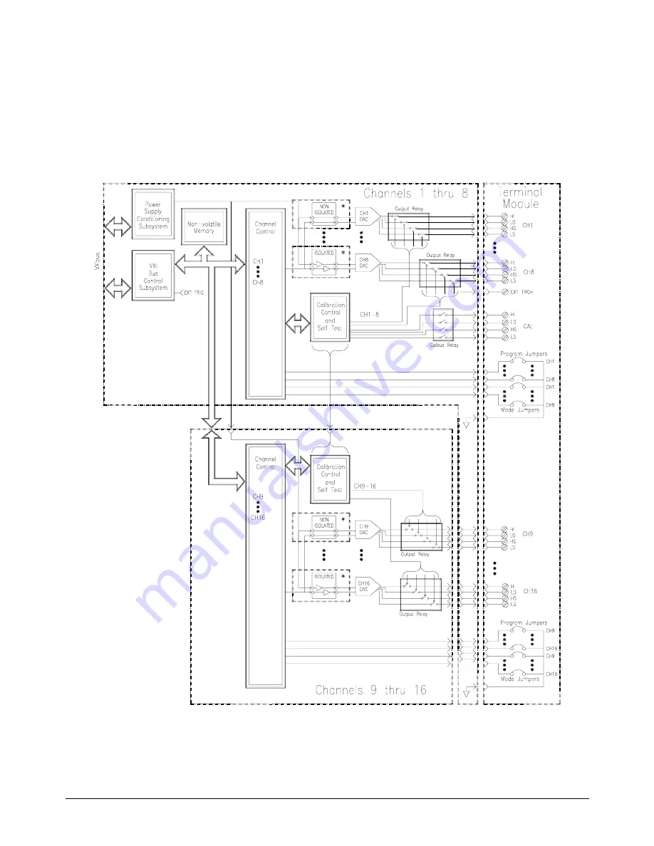
The HP E1418A provides great flexibility in configuration. This functional
description will help you become familiar with the various configurations
and how the module is structured. A functional block diagram is shown in
Figure 1-2.
*
Each channel MUST have either an isolated or non-isolated plug-on module installed. Channels may be configured
using any combination of Isolated and Non-Isolated plug-on modules.
Figure 1-2. A Functional Block Diagram
16 Module Setup and Installation
Chapter 1
Summary of Contents for E1418A
Page 6: ...Notes 6 Contents HP E1418A 8 16 Channel D A Converter Module ...
Page 10: ...Notes 10 HP E1418A User s Manual ...
Page 12: ...12 HP E1418A User s Manual ...
Page 105: ...TRIGger 105 HP E1418A SCPI Command Reference Chapter 3 ...
Page 111: ...Notes HP E1418A Command Quick Reference 111 HP E1418A SCPI Command Reference Chapter 3 ...
Page 135: ...135 HP E1418A Register Based Programming Appendix B ...
Page 157: ...Notes 156 HP E1418A Error Messages Appendix C ...
Page 170: ...Notes Appendix D Voltage Current Output Adjustment 169 ...
Page 174: ...Figure E 1 8 Channel Disassembly 172 Configuration and Disassembly Appendix E ...
Page 175: ...Figure E 2 16 Channel Disassembly Appendix E Configuration and Disassembly 173 ...
Page 192: ...Notes 192 HP E1418A 8 16 Channel D A Converter Module Index ...


