HP-00007-01, Appendix 3 02-Jun-2005
HP Restricted
Page 4
3.2 Illustrations
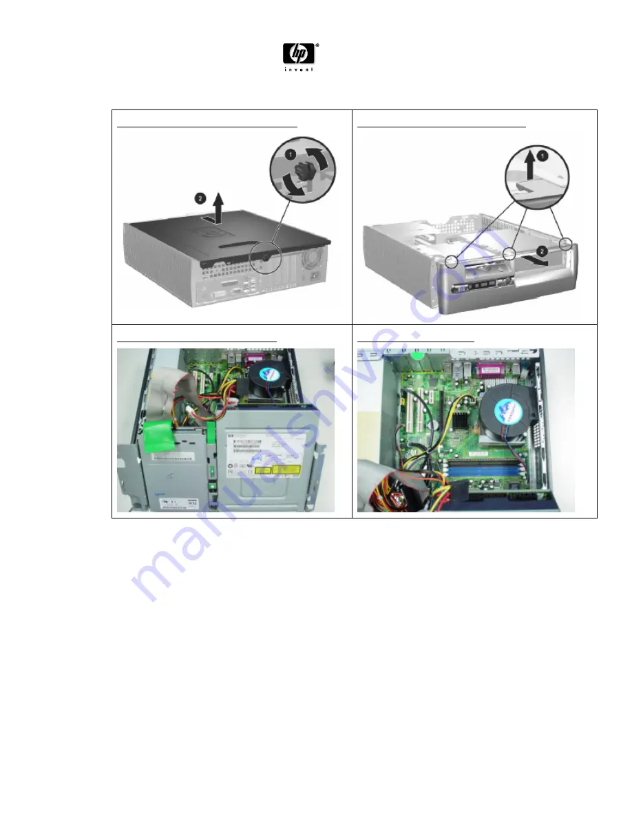
FIGURE 1: Removing the access panel
FIGURE 2: Removing the front bezel
FIGURE 3: Rotating the drive cage
FIGURE 4: System board
Page 1: ...ater than 10 square cm 2 sys board P S board Batteries All types including standard alkaline and lithium coin or button style batteries 1 Mercury containing components For example mercury in lamps display backlights scanner lamps switches batteries 0 Liquid Crystal Displays LCD with a surface greater than 100 square cm Includes background illuminated displays with gas discharge lamps 0 Cathode Ray...
Page 2: ... 4 below 5 To remove the heatsink assembly see Figures 5 6 below a Loosen the two captive screws that secure the heatsink to the system board b Twist the heatsink slightly to break the bond between it and the processor then and then lift the heatsink from the processor 6 To remove the processor see Figure 7 below a Rotate the socket handle to its fully open position b Lift the processor from the s...
Page 3: ...acitors C4 C5 solder joint see Figure 16 below using dikes see Figure 17 below and then remove the capacitors 9 Cut the capacitor C11 solder joint using dikes and then remove the capacitor see Figure 18 below BATTERY 1 Locate the battery and battery holder on the system board 2 Depending on the type of battery holder on the system board complete the following instructions to replace the battery Ty...
Page 4: ...HP 00007 01 Appendix 3 02 Jun 2005 HP Restricted Page 4 3 2 Illustrations FIGURE 1 Removing the access panel FIGURE 2 Removing the front bezel FIGURE 3 Rotating the drive cage FIGURE 4 System board ...
Page 5: ...5 HP Restricted Page 5 FIGURE 5 Removing the heatsink FIGURE 6 Removing the heatsink assembly FIGURE 7 Removing the processor FIGURE 8 System board screw locations FIGURE 9 Removing the system board FIGURE 10 Removing the power supply ...
Page 6: ...1 Appendix 3 02 Jun 2005 HP Restricted Page 6 FIGURE 11 Tie wrap FIGURE 12 Power supply with cover removed FIGURE 13 Switch cables FIGURE 14 Inlet cables FIGURE 15 Power supply PCA FIGURE 16 C4 and C5 capacitors ...
Page 7: ...HP 00007 01 Appendix 3 02 Jun 2005 HP Restricted Page 7 FIGURE 17 Dikes FIGURE 18 C11 capacitor FIGURE 19 Type 1 battery holder FIGURE 20 Type 2 battery holder ...