


-200
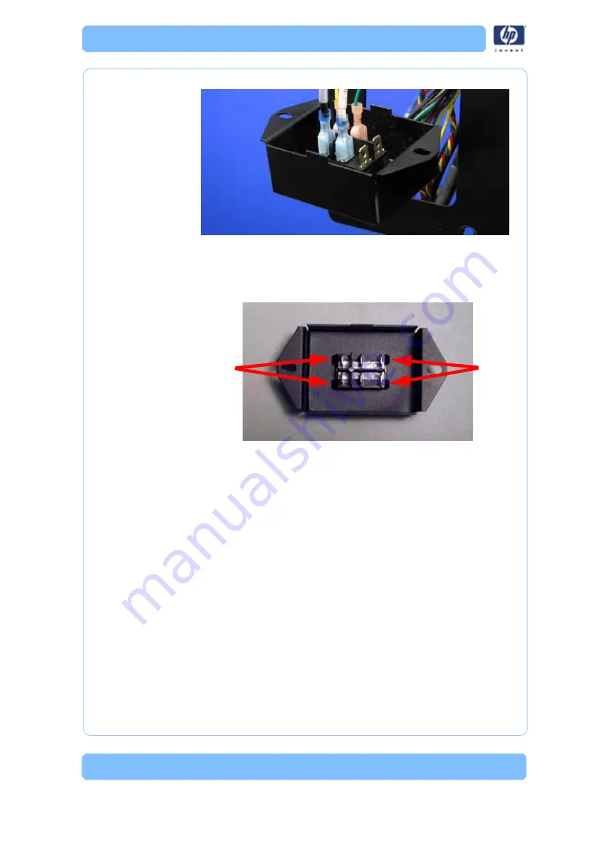
Figure 117: Power switch connector locations
8. Press the Power Switch tabs in and push it out of the housing. See
Figure 118: Removing the power switch
Installing the power switch
1. Push the power switch into place on the power switch housing.
2. Connect the yellow NC wire to the spade connector labeled “2a”.
3. Connect the green COM wire to the spade connector labeled “2”.
4. Connect the black SW3 wire to the spade connector labeled “1a”.
5. Connect the white SW2 wire to the spade connector labeled “3”.
6. Align the power switch housing with the mounting holes.
7. Using a
5
⁄
16
” nut driver or standard screwdriver, reinstall the 2 mounting
screws.
8. Reinstall the left side panel. See
“Installing the side panels” on
9. Install the top panel. See
“Installing the top panel” on page 162
Press tabs to
release
Press tabs to
release
Summary of Contents for DESIGNJET 3D
Page 1: ...HP Designjet 3D HP Designjet Color 3D Service Guide ...
Page 3: ......
Page 4: ... 3 ...
Page 16: ... 12 ...
Page 40: ... 24 ...
Page 52: ... 36 ...
Page 70: ... 54 ...
Page 74: ... 58 ...
Page 90: ... 74 ...
Page 172: ... 156 ...
Page 314: ... 298 Figure 272 HP Designjet 3D measurement points and worksheet BL FL FR BR ...
Page 315: ... 299 Figure 273 HP Designjet Color 3D measurement points and worksheet BL FL FR BR ...
Page 349: ... 333 Figure 316 HP Designjet 3D measurement points and worksheet BL FL FR BR ...
Page 350: ... 334 Figure 317 HP Designjet Color 3D measurement points and worksheet BL FL FR BR ...
Page 352: ... 336 ...
Page 404: ... 388 Figure 402 HP Designjet 3D measurement points and worksheet BL FL FR BR ...
Page 405: ... 389 Figure 403 HP Designjet Color 3D measurement points and worksheet BL FL FR BR ...
Page 458: ... 442 ...


