


-197
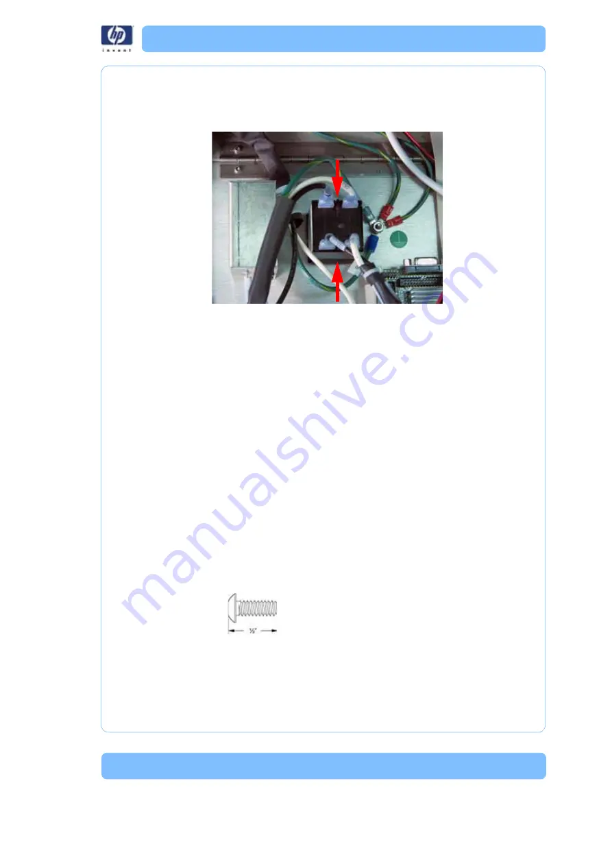
5. Squeeze the tabs on the circuit breaker and push through the electronics
bay panel. See
Figure 113: Removing the circuit breaker
Installing the circuit breaker
1. Push the circuit breaker through the electronics bay panel until it locks in
place.
2. Reconnect the CB1 and CB2 spade connectors to the circuit breaker.
3. Reconnect the Load and CB1 spade connectors to the circuit breaker.
4. Close the electronics bay. See
“Closing the electronics bay” on
AC Input
Required Tools
•
5
⁄
16
” nut driver or standard screwdriver.
• Phillips screwdriver
Hardware
•
1
⁄
2
” x 6mm Phillips pan head screws (x2)
Press tabs and push the
circuit breaker through
the panel
Summary of Contents for DESIGNJET 3D
Page 1: ...HP Designjet 3D HP Designjet Color 3D Service Guide ...
Page 3: ......
Page 4: ... 3 ...
Page 16: ... 12 ...
Page 40: ... 24 ...
Page 52: ... 36 ...
Page 70: ... 54 ...
Page 74: ... 58 ...
Page 90: ... 74 ...
Page 172: ... 156 ...
Page 314: ... 298 Figure 272 HP Designjet 3D measurement points and worksheet BL FL FR BR ...
Page 315: ... 299 Figure 273 HP Designjet Color 3D measurement points and worksheet BL FL FR BR ...
Page 349: ... 333 Figure 316 HP Designjet 3D measurement points and worksheet BL FL FR BR ...
Page 350: ... 334 Figure 317 HP Designjet Color 3D measurement points and worksheet BL FL FR BR ...
Page 352: ... 336 ...
Page 404: ... 388 Figure 402 HP Designjet 3D measurement points and worksheet BL FL FR BR ...
Page 405: ... 389 Figure 403 HP Designjet Color 3D measurement points and worksheet BL FL FR BR ...
Page 458: ... 442 ...


