background image

A Warranty and regulatory information

For important safety, environmental, and regulatory information, see

Safety and Compliance

Information for Server, Storage, Power, Networking, and Rack Products

, available at

www.hpe.com/support/Safety-Compliance-EnterpriseProducts

.

Warranty information

HPE ProLiant and x86 Servers and Options

www.hpe.com/support/ProLiantServers-Warranties

HPE Enterprise Servers

www.hpe.com/support/EnterpriseServers-Warranties

HPE Storage Products

www.hpe.com/support/Storage-Warranties

HPE Networking Products

www.hpe.com/support/Networking-Warranties

Regulatory information

Belarus Kazakhstan Russia marking

Manufacturer and Local Representative Information

Manufacturer information:

Hewlett Packard Enterprise Company, 3000 Hanover Street, Palo Alto, CA 94304 U.S.

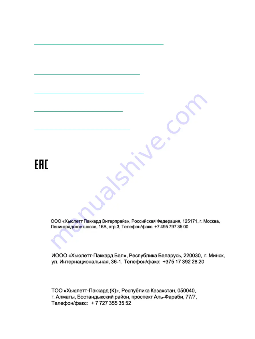
Local representative information Russian:

Russia

:

Belarus

:

Kazakhstan

:

46

Warranty and regulatory information

Summary of Contents for D3600

Page 1: ... This guide is intended for users who maintain the HPE D3600 3700 Disk Enclosures Some of the actions described are more appropriate to Hewlett Packard Enterprise service specialists and require an Support login Part Number 734754 001R Published November 2015 Edition 2 ...

Page 2: ...ein should be construed as constituting an additional warranty Hewlett Packard Enterprise shall not be liable for technical or editorial errors or omissions contained herein Confidential computer software Valid license from Hewlett Packard Enterprise required for possession use or copying Consistent with FAR 12 211 and 12 212 Commercial Computer Software Computer Software Documentation and Technic...

Page 3: ...a drive 16 Replacing a drive 16 Removing and replacing I O Cables 17 Removing and replacing the I O module 18 Removing and replacing a power supply 18 Removing and replacing the fan module 19 Removing and replacing the fan control card 21 Removing and replacing the enclosure 22 Removing and replacing the Power Distribution Board 23 Removing and replacing the UID health module 24 Removing and repla...

Page 4: ... 42 Physical specifications 42 Power and environmental specifications 42 Acoustic noise levels 42 6 Support and other resources 44 Accessing Hewlett Packard Enterprise Support 44 Accessing updates 44 Websites 44 Customer self repair 45 Remote support 45 Documentation feedback 45 A Warranty and regulatory information 46 Warranty information 46 Regulatory information 46 Belarus Kazakhstan Russia mar...
Page 5: ...ch enclosure is shipped with an optional Digital Rain bezel which customers can install as needed The graphics in this guide are portrayed without the bezel for clarity NOTE Depending on your disk enclosure model and controller installation environment one or more disk enclosures can be cascaded from the disk enclosure that is connected to the controller For more information see the QuickSpecs for...

Page 6: ...uct safety and operating instructions Always refer to the documentation printed or electronic supplied with your product If there is a conflict between this document and the product documentation the product documentation takes precedence Observe all warnings on the product and in the operating instructions to reduce the risk of bodily injury electric shock fire and damage to the equipment General...

Page 7: ...ting up the system or handling parts A discharge of static electricity from a finger or other conductor may damage system boards or other static sensitive devices This type of damage may reduce the life expectancy of the device To prevent electrostatic damage Avoid hand contact by transporting and storing products in static safe containers Keep electrostatic sensitive parts in their containers unt...

Page 8: ...8 Removal and replacement procedures ...

Page 9: ...es Use caution and get help to lift and stabilize enclosures during installation or removal especially when the enclosure is not fastened to the rack Never stack an enclosure on top of another enclosure Never place equipment on top of an enclosure Never place an enclosure on a surface that cannot support up to 163 3 kg 360 0 lb WARNING To reduce the risk of personal injury or damage to the equipme...

Page 10: ...vers and touching internal components Do not use conductive tools that could bridge live parts Remove all watches rings or loose jewelry when working in hot plug areas of an energized server and storage products Do not attempt to defeat safety interlocks where provided Some products have covers or doors to access hot plug components and may allow access to hazardous energy circuits or moving fans ...

Page 11: ...ed electrical outlet that is easily accessible at all times Power supplies Hot plug power supplies are not designed to be removed or installed with AC power connected to the power supply To reduce the risk of electric shock or damage to the equipment when handling hot plug power supplies Install the power supply before connecting the power cord to the power supply Unplug the power cord before remo...

Page 12: ... on standby button Power flows to the enclosure immediately upon connecting to a live power source 2 Once power is applied to the power supplies the enclosure starts running The power on LED turns solid green 3 Wait a few minutes for the disk enclosures to complete their startup routines CAUTION If power is applied to the server before the disk enclosures complete their startup routine the server ...

Page 13: ...llation procedures and remove and reinsert the module Front panel LEDs Fault conditions Operating condition Startup condition Indicator N A 1 HDD Solid green Solid green 2 Bi color System Health LED Flashing amber non critical error Solid amber critical failure The UID is a locator LED activated by pressing the rear or the front UID buttons 3 Blue UID LED Fan module Fault conditions Operating cond...

Page 14: ...Off Solid green Blinking green 5 Health Blinking or solid amber Off 6 Fault Power supply module Definition Status Indicator Powering up Flashing green Status LED Normal operation Solid green No power or fault Unlit Verifying the status of the disk drives Both the HPE G8 LFF and SFF drive carrier system uses I2C communication for drive authentication failure and configuration info activity animatio...

Page 15: ... predicts the drive will fail Flashing amber The drive has failed Solid amber The drive is not configured by a RAID controller Off Hard drive blanks To maintain the proper enclosure air flow a disk drive or a disk drive blank must be installed in each drive bay The disk drive blank maintains proper airflow within the disk enclosure Hard drive Depending on the types of hard disk drives HDDs you are...

Page 16: ... number If only one hard drive is used install it in the bay with the lowest device number Disk drives are hot pluggable SAS and SATA disk drives may be installed in the same enclosure but cannot be included in the same RAID logical volume Removing a drive CAUTION To prevent improper cooling and thermal damage operate the enclosure only when all bays are populated with either a component or a blan...

Page 17: ...is seated properly and receiving power 3 If you are replacing a drive confirm that the replacement drive matches the drive that is being replaced 4 Determine the status of the hard drive IMPORTANT For proper airflow and cooling a drive blank must remain installed in all unused drive bays Removing and replacing I O Cables NOTE If the cable is malfunctioning check the LED displays on the I O module ...

Page 18: ...ive retaining thumbscrew 1 and swing out the hood latch 2 3 Slide out the I O module 3 and set aside 4 Then slide the replacement I O module into the correct bay and swing in the hood latch until it closes 5 Re tighten the captive retainer thumbscrew 6 Replace the two I O cables 7 Read the LEDs to confirm the unit is operating See I O module LEDs page 14 Removing and replacing a power supply 1 Rem...

Page 19: ... Replace the power cable 5 Confirm that the system is in normal state See Verifying the operating status of the disk enclosures page 13 Removing and replacing the fan module 1 Pinch the release buttons and slide the module out 2 Slide in new fan module until it clicks into place Removing and replacing the fan module 19 ...

Page 20: ...3 Confirm that the system is in normal state See Verifying the operating status of the disk enclosures page 13 20 Removal and replacement procedures ...

Page 21: ...placing the enclosure page 22 6 Pull hood latch up and back 1 and 2 and lift enclosure cover up and remove 3 7 Remove fan control card cable 1 8 Loosen the T 15 captive thumbscrew 2 9 Slide the fan control card sideways to free it from the retaining pins and lift out 3 10 Insert the new fan control card and slide sideways to engage it with the retaining pins 11 Re tighten the captive T 15 thumbscr...

Page 22: ... I O modules See Removing and replacing the I O module page 18 7 Remove both fan modules See Removing and replacing the fan module page 19 8 Loosen the captive CTO screws behind the latch on the front left and right bezel ears of the chassis 1 9 Loosen the rear CTO hold down bracket 10 Slide the enclosure out of the rails 2 and set it on a secure surface WARNING Always use at least two people to l...

Page 23: ... front of enclosure to remove 2 9 Loosen the T 15 captive thumbscrew on the Power Distribution Board 10 Slide the Power Distribution Board toward the front of the enclosure and lift out of the enclosure 11 Replace Power Distribution Board in the enclosure and slide toward the back of the enclosure 12 Tighten the captive T 15 screw to secure the Power Distribution Board 13 Attach power cables to th...

Page 24: ...22 5 Pull up hood latch and remove enclosure cover 6 Disconnect the rear UID Health module cable from the backplane 7 Remove the UID Health module retaining screw 1 8 Slide out the UID Health module 2 while guiding the cable through the enclosure WARNING The UID cable is adhered to the chassis Care should be taken to remove it The cable could become unusable 9 Replace the UID Health module by slid...

Page 25: ...Back up data if required 1 Unplug the power cables 2 Remove I O cables See Removing and replacing I O Cables page 17 3 Label drives for removal 4 Remove the drives See Removing a drive page 16 5 Remove power supplies See Removing and replacing a power supply page 18 6 Remove I O modules See Removing and replacing the I O module page 18 7 Remove fan modules See Removing and replacing the fan module...

Page 26: ...it there are 6 or 8 locating pins 18 Replace the eight T 10 drive cage retaining screws 19 Connect the two UID Health module cables 20 Connect the power cables 21 Connect the fan control card cables 22 Replace the cover and press lever down to secure 23 Replace the enclosure in the rack See Removing and replacing the enclosure page 22 24 Replace the I O modules See Removing and replacing the I O m...

Page 27: ... disk enclosures switches and servers are of differing depths if you have more than one of a device mount those devices adjacent to one another to accommodate working behind the rack WARNING To reduce the risk of personal injury or damage to the equipment be sure that At least two people lift the storage system during removal or installation if the weight exceeds 22 7 kg 50 lb If the system is bei...

Page 28: ...to engage the spring hook with the RETMA column in the same manner as the rear spring hook NOTE Make sure that the respective guide pins for the square or round hole rack align properly into RETMA column hole spacing 5 Secure rear of rack rail to the RETMA column with either the round or square hole shoulder screws provided in the package 6 Secure front of rail to the front RETMA column using the ...

Page 29: ...kets by sliding the tab with the arrow pointed forward 1 into the corresponding slot on the left and right side of the rear of the chassis Use the black headed thumb screw to secure tightly to the rail 2 Installing the rail kit 29 ...

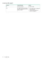
Page 30: ...g the power supply LEDs If necessary remove and reinstall the power supplies to verify that they are seated properly b Remove and inspect AC power cords from both power supplies and reconnect them Diagnostic steps Is the enclosure front fault LED amber Actions Possible Reasons Answer No action required System functioning properly No Yes Be sure that the Front Status and UID module is undamaged and...

Page 31: ... provider for assistance Is the power supply LED green Actions Possible Reasons Answers No Remove and inspect the AC power cords from both power supplies and reconnect them Power cords not connected or AC power is unavailable Power supply not functioning properly Replace with a known good power supply No action required The component is functioning normally Yes Is the I O module fault LED amber Po...

Page 32: ... action required Functioning properly No Fan might not be inserted properly might have a damaged connector or might have failed Yes Be sure that the fan is undamaged and is fully seated Contact an authorized service provider for assistance 32 Troubleshooting ...

Page 33: ... fails all non fault tolerant RAID0 logical drives in the same array also fail RAID1 0 configurations can tolerate multiple drive failures as long as no failed drives are mirrored to one another with no spares assigned RAID5 configurations can tolerate one drive failure with no spares assigned RAID6 with ADG configurations can tolerate simultaneous failure of two drives with no spares assigned Com...

Page 34: ...ives that are not mirrored to other removed or failed drives can be simultaneously replaced offline without data loss Automatic data recovery rebuild When you replace a disk drive in an array the controller uses the fault tolerance information on the remaining drives in the array to reconstruct the missing data the data that was originally on the replaced drive and write it to the replacement driv...

Page 35: ...ecovery of unsaved data In any case locate the faulty drive replace it and restore data from backup Handling disk drive failures If the controller was configured with hardware fault tolerance complete the following steps after a disk drive failure 1 Determine which physical drive failed On hot plug drives an amber drive failure LED illuminates 2 If the unit containing the failed drive does not sup...

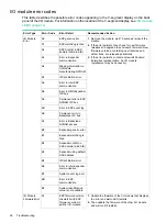
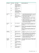
Page 36: ...An I O module replacement may be necessary Missing information in IO Module manufacturing NVRAM A4 I2C arbitration error A5 Error in inter ESP communication A6 Error in GPIO Expander I2C bus A8 Permanent error in ESP NVRAM I2C bus A9 Error in ESP event log AD Permanent error in Backplane I2C bus AE Error in Backplane NVRAM access AF Expander generic error B0 Expander watchdog is fired B1 Expander ...

Page 37: ...x it Error in disk drive BB Disk Drive Error There is at least one non authentic HPE disk drive on the system Non authentic disks may not work properly on this system Not authentic drive in the enclosure BC Check your storage administration software for more information about the problem detected and how to properly fix it Generic temperature error C0 Thermal Control Error 1 Remove the module wait...

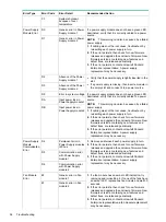
Page 38: ...ule 2 DB 1 If cabling was not the root cause troubleshoot by reinserting each power supply in turn 2 If the error persists then check for new firmware releases and upgrade the enclosure firmware New firmware versions containing new features and defect fixes are released periodically 3 If the error persists contact an Hewlett Packard Enterprise representative A power supply replacement may be neces...

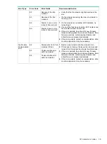
Page 39: ...w firmware versions containing new features and defect fixes are released periodically 4 If the error persists contact an representative a fan module replacement may be necessary Permanent error in Fan modules I2C bus E4 Fan Module Communication Error 1 Remove and reinsert each fan module in turn 2 If this does not resolve the issue then remove and reinsert the I O module that shows the status cod...

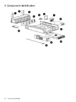
Page 40: ...4 Component identification 40 Component identification ...

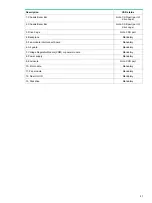
Page 41: ... Ear Not a CSR part 3 Drive Cage Mandatory 4 Backplane Mandatory 5 Fan module interconnect board Mandatory 6 Air guard Mandatory 7 Voltage Regulator Module VRM or power module Mandatory 8 Power supply Not a CSR part 9 Enclosure Mandatory 10 I O module Mandatory 11 Fan module Mandatory 12 Rear Unit ID Mandatory 13 Disk drive 41 ...

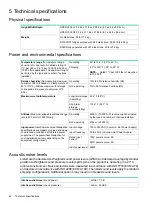
Page 42: ...6 F 38 7 C Short term storage non operating 3048 m 10 000 ft This value might be limited by the type and number of options installed Operating Altitude Maximum allowable altitude change rate is 457 m min 1500 ft min 9144 m 30 000 ft Non operating 100 to 240 VAC Common slot Power Supply Input voltage Input power Input Power and Heat Dissipation specifications are maximum values and apply 50 to 60 H...

Page 43: ...LWAd 7 0 B Operating Acoustic Noise sound power LpAm 53 dBA Operating Acoustic Noise sound pressure Acoustic noise levels 43 ...

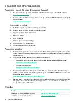
Page 44: ...roduct documentation to identify the recommended software update method To download product updates go to either of the following Hewlett Packard Enterprise Support Center Get connected with updates page www hpe com support e updates Software Depot website www hpe com support softwaredepot To view and update your entitlements and to link your contracts and warranties with your profile go to the He...

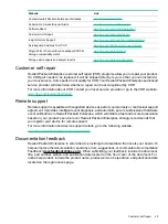
Page 45: ...tact your local service provider or go to the CSR website www hpe com support selfrepair Remote support Remote support is available with supported devices as part of your warranty or contractual support agreement It provides intelligent event diagnosis and automatic secure submission of hardware event notifications to Hewlett Packard Enterprise which will initiate a fast and accurate resolution ba...

Page 46: ...rt ProLiantServers Warranties HPE Enterprise Servers www hpe com support EnterpriseServers Warranties HPE Storage Products www hpe com support Storage Warranties HPE Networking Products www hpe com support Networking Warranties Regulatory information Belarus Kazakhstan Russia marking Manufacturer and Local Representative Information Manufacturer information Hewlett Packard Enterprise Company 3000 ...

Page 47: ...ear counting from within each new decade with 2000 as the starting point for example 238 2 for 2002 and 38 for the week of September 9 In addition 2010 is indicated by 0 2011 by 1 2012 by 2 2013 by 3 and so forth YYWW where YY indicates the year using a base year of 2000 for example 0238 02 for 2002 and 38 for the week of September 9 Turkey RoHS material content declaration Ukraine RoHS material c...

Reviews: