


Removal and replacement procedures
Maintenance and Service Guide
4–41
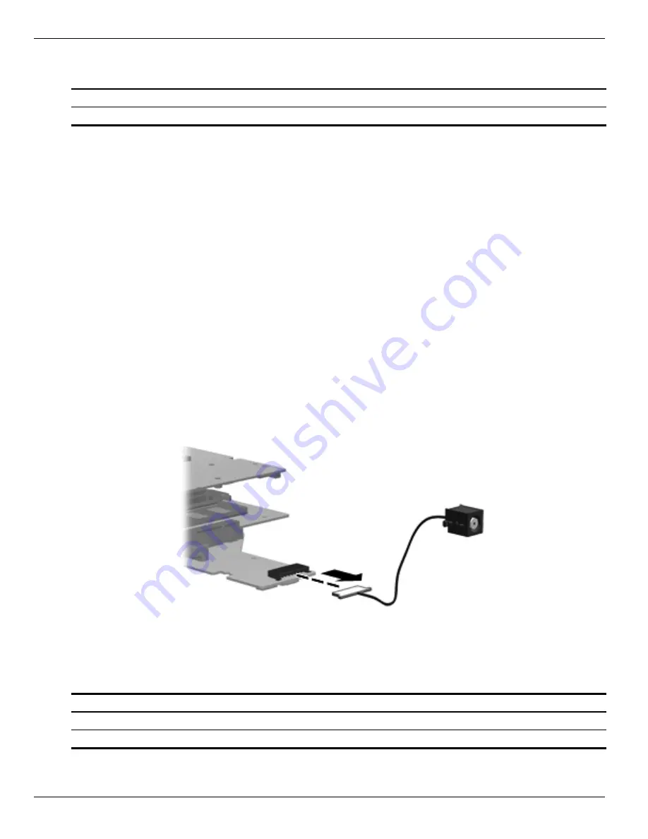
Power connector
Before removing the power connector cable:
1. Shut down the computer. If you are unsure whether the computer is off or in Hibernation, turn the computer on,
and then shut it down through the operating system.
2. Disconnect all external devices connected to the computer.
3. Disconnect the power from the computer by first disconnecting the power cord from the AC outlet and then
disconnecting the AC adapter from the computer.
4. Remove the battery (see
“Battery” on page 4-7
).
5. Remove the hard drive (see
“Hard drive” on page 4-8
).
6. Remove the memory module (see
“Memory module” on page 4-11
).
7. Remove the wireless module (see
“Wireless module” on page 4-13
).
8. Remove the optical drive (see
“Optical drive” on page 4-16
).
9. Remove the keyboard (see
“Keyboard” on page 4-18
).
10. Remove the top cover (see
“Top cover” on page 4-23
).
11. Remove the display assembly (see
“Display assembly” on page 4-28
).
Remove the power connector cable by disconnecting the cable connector from the system board.
Reverse this procedure to install the power connector cable.
Bluetooth module
Before removing the Bluetooth module:
Description
Spare part number
Power connector (includes cable)
600719-001
Description
Spare part number
Bluetooth module
537921-001
Bluetooth module cable
602538-001
Summary of Contents for Compaq Presario CQ72
Page 2: ......
Page 6: ......
Page 10: ...vii Maintenance and Service Guide Contents ...
Page 14: ...1 4 Maintenance and Service Guide Product description ...
Page 26: ...3 2 Maintenance and Service Guide Illustrated parts catalog Computer major components ...
Page 32: ...3 8 Maintenance and Service Guide Illustrated parts catalog Display assembly components ...
Page 42: ...3 18 Maintenance and Service Guide Illustrated parts catalog ...
Page 110: ...6 6 Maintenance and Service Guide Specifications ...
Page 120: ...8 6 Maintenance and Service Guide Connector pin assignments ...


