HP-00007-01, Appendix 3 22-Mar-2006
HP Restricted
Page 6
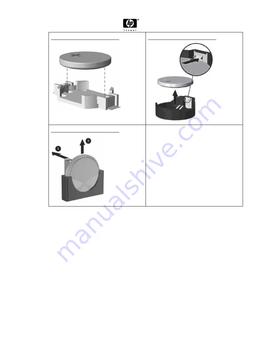
FIGURE 11: Type 1 battery holder
FIGURE 12: Type 2 battery holder
FIGURE 13: Type 3 battery holder
Page 1: ...quare cm 3 1 sys board 2 P S board Batteries All types including standard alkaline and lithium coin or button style batteries 1 Mercury containing components For example mercury in lamps display backlights scanner lamps switches batteries 0 Liquid Crystal Displays LCD with a surface greater than 100 square cm Includes background illuminated displays with gas discharge lamps 0 Cathode Ray Tubes CRT...
Page 2: ...ttom and lift it off the unit 2 Remove the front bezel see Figure 1 below a Pull outward on all three tabs on the left side of the bezel 1 b Rotate the bezel off the chassis 2 beginning with the left side then the right side 3 Disconnect the power and data cables from the back of all installed drives 4 Disconnect all cables from the system board 5 Remove the heatsink from the system board see Figu...
Page 3: ...astic cable clamp that secures the cables to the chassis see Figure 7 below b Remove the four screws that secure the power supply PCA to the chassis see Figure 8 9 below c Using diagonal cutters dikes cut all cables connected to the PCA 2 to switch 2 to PC inlet 2 to power supply fan see Figure 10 below d Remove the power supply PCA from the power supply chassis BATTERY Locate the battery and batt...
Page 4: ...007 01 Appendix 3 22 Mar 2006 HP Restricted Page 4 3 2 ILLUSTRATIONS Figure 1 Removing the front bezel Figure 2 Removing the heatsink Figure 3 Removing the system board Figure 4 Power supply screw locations ...
Page 5: ...e 5 Figure 5 Cut the plastic cable clamp Figure 6 Power supply cover screw locations Figure 7 Cut the plastic cable clamp Figure 8 Power supply PCA screw locations Figure 9 Power supply PCA screw locations Figure 10 Cut all cables connected to the board ...
Page 6: ...HP 00007 01 Appendix 3 22 Mar 2006 HP Restricted Page 6 FIGURE 11 Type 1 battery holder FIGURE 12 Type 2 battery holder FIGURE 13 Type 3 battery holder ...