EL-MF877-00 Page 7 Template Revision A
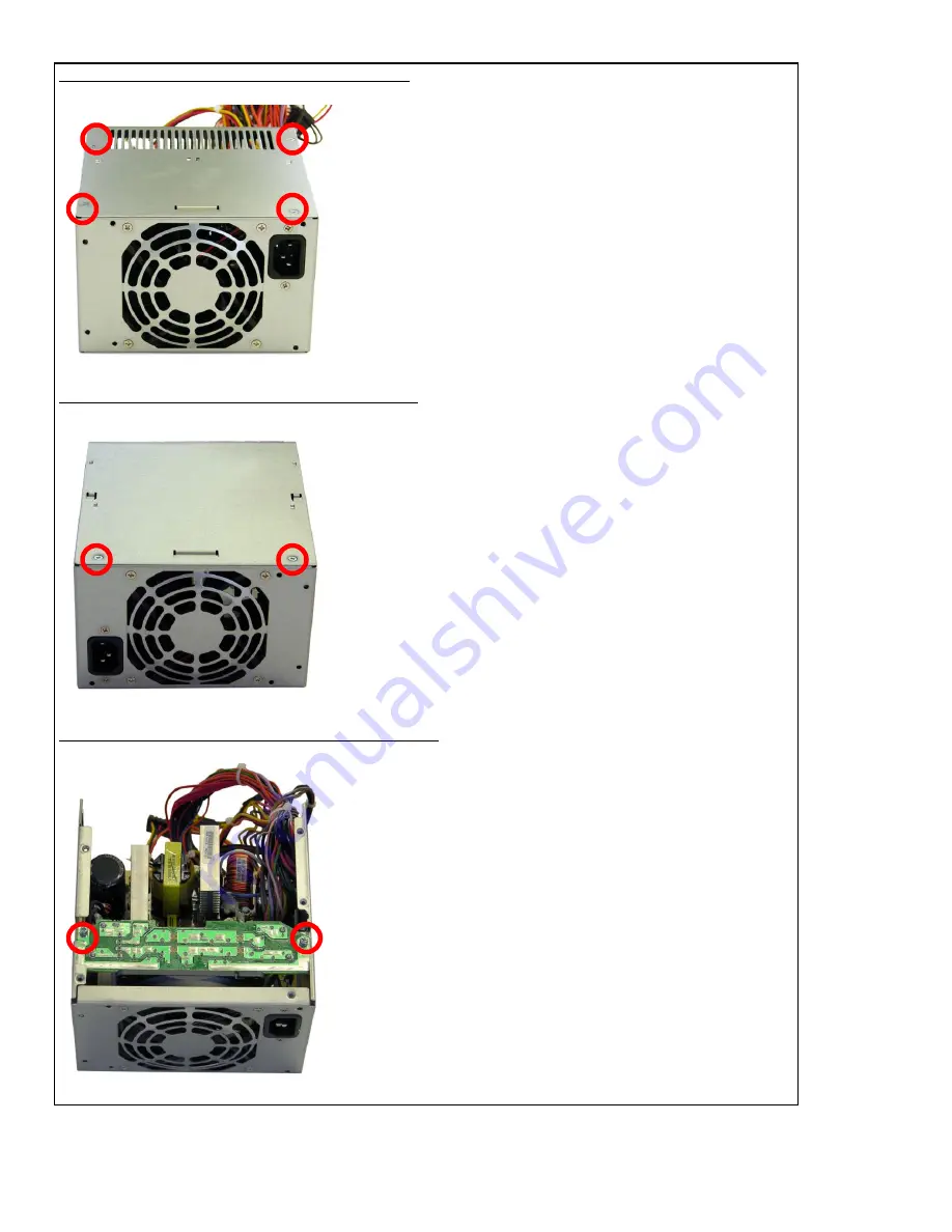
FIGURE 9: POWER SUPPLY 1: Cover screw locations
FIGURE 10: POWER SUPPLY 1: Cover screw locations
FIGURE 11: POWER SUPPLY 1: Top PCA screw locations
Page 1: ...rcuit Boards PCB or Printed Circuit Assemblies PCA With a surface greater than 10 sq cm 2 to 4 1 sys board 1 to 3 P S PCAs Batteries All types including standard alkaline and lithium coin or button style batteries 1 Mercury containing components For example mercury in lamps display backlights scanner lamps switches batteries Liquid Crystal Displays LCD with a surface greater than 100 sq cm Include...
Page 2: ...nd size of the tools that would typically be used to disassemble the product to a point where components and materials requiring selective treatment can be removed Tool Description Tool Size if applicable Description 1 Phillips screwdriver Description 2 Dikes Description 3 Torx screwdriver T 15 3 0 Product Disassembly Process 3 1 List the basic steps that should typically be followed to remove com...
Page 3: ...e the power supply PCA from the power supply chassis h Cut the small PCA from the large power supply PCA see Figure 13 i Cut 4 capacitors from the PCA as shown in Figure 13 POWER SUPPLY 2 a Using dikes cut the plastic clamp that secures the wires to the power supply cover b Using a phillips screwdriver remove the four screws that secure the cover to the power supply chassis two screws on top two s...
Page 4: ...EL MF877 00 Page 4 Template Revision A FIGURE 1 Removing the access panel FIGURE 2 Removing the front bezel FIGURE 3 Type 1 battery holder ...
Page 5: ...EL MF877 00 Page 5 Template Revision A FIGURE 4 Type 2 battery holder FIGURE 5 Type 3 battery holder FIGURE 6 Removing the system board ...
Page 6: ...EL MF877 00 Page 6 Template Revision A FIGURE 7 Removing the power supply screws FIGURE 8 Removing the power supply from the chassis ...
Page 7: ...EL MF877 00 Page 7 Template Revision A FIGURE 9 POWER SUPPLY 1 Cover screw locations FIGURE 10 POWER SUPPLY 1 Cover screw locations FIGURE 11 POWER SUPPLY 1 Top PCA screw locations ...
Page 8: ...EL MF877 00 Page 8 Template Revision A FIGURE 12 POWER SUPPLY 1 Large PCA screw locations FIGURE 13 POWER SUPPLY 1 Capacitors 4 to cut y ...
Page 9: ...EL MF877 00 Page 9 Template Revision A FIGURE 14 POWER SUPPLY 2 Cover screw locations FIGURE 15 POWER SUPPLY 2 Cover screw locations FIGURE 16 POWER SUPPLY 2 PCA screw locations ...
Page 10: ...EL MF877 00 Page 10 Template Revision A FIGURE 17 POWER SUPPLY 2 Capacitors 5 and small PCA to cut FIGURE 18 POWER SUPPLY 3 Cover screw locations FIGURE 19 POWER SUPPLY 3 Cover screw locations ...
Page 11: ...EL MF877 00 Page 11 Template Revision A FIGURE 20 POWER SUPPLY 3 Top PCA screw locations FIGURE 21 POWER SUPPLY 3 Large PCA screw locations FIGURE 22 POWER SUPPLY 3 Capacitors 9 and small PCA to cut ...
Page 12: ...EL MF877 00 Page 12 Template Revision A ...