background image

Table 2-1

  Right-side components and their descriptions (continued)

Component

Description

(4)

AC adapter and battery light 

(continued)

Off: The battery is not charging.

(5)

USB SuperSpeed port with HP Sleep and Charge

Connects a USB device, provides high-speed data transfer, and 
even when the computer is in Sleep mode, charges most products 
such as a cell phone, camera, activity tracker, or smartwatch.

Left side

Table 2-2

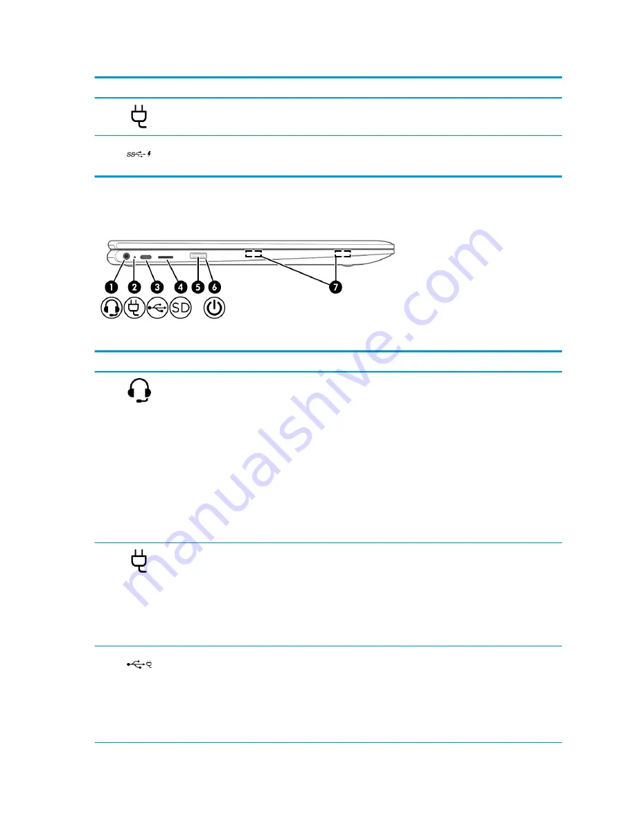
  Left-side components and their descriptions

Component

Description

(1)

Audio-out (headphone)/Audio-in (microphone) 
combo jack

Connects optional powered stereo speakers, headphones, 
earbuds, a headset, or a television audio cable. Also connects an 
optional headset microphone. This jack does not support optional 
standalone microphones.

WARNING!

To reduce the risk of personal injury, adjust 

the volume before putting on headphones, earbuds, or a headset. 
For additional safety information, see the 

Regulatory, Safety, and 

Environmental Notices

.

To access this guide:

Select the Start button, select HP Help and Support, and 
then select HP Documentation.

NOTE:

When a device is connected to the jack, 

the computer speakers are disabled.

(2)

AC adapter and battery light

White: The AC adapter is connected and the battery is 
fully charged.

Blinking white: The AC adapter is disconnected and the 
battery has reached a low battery level.

Amber: The AC adapter is connected and the battery 
is charging.

Off: The battery is not charging.

(3)

USB Type-C power connector and port

Connects an AC adapter that has a USB Type-C connector, 
supplying power to the computer and, if needed, charging the 
computer battery.

– and –

Connects a USB device that has a Type-C connector, such as a cell 
phone, camera, activity tracker, or smartwatch, and provides 
data transfer.

4

Chapter 2   External component identification

Summary of Contents for Chromebook x360 12b

Page 1: ...Maintenance and Service Guide HP Chromebook x360 12b IMPORTANT This document is intended for HP authorized service providers only ...

Page 2: ...irst Edition August 2019 Document Part Number L69445 001 Product notice This guide describes features that are common to most models Some features may not be available on the computer Not all features are available in all editions or versions of Windows Systems may require upgraded and or separately purchased hardware drivers software or BIOS update to take full advantage of Windows functionality ...

Page 3: ...e device only on a hard flat surface Do not allow another hard surface such as an adjoining optional printer or a soft surface such as pillows or rugs or clothing to block airflow Also do not allow the AC adapter to contact the skin or a soft surface such as pillows or rugs or clothing during operation The device and the AC adapter comply with the user accessible surface temperature limits iii ...

Page 4: ...iv Safety warning notice ...

Page 5: ... 16 4 Removal and replacement procedures preliminary requirements 17 Tools required 17 Service considerations 17 Plastic parts 17 Cables and connectors 17 Drive handling 18 Electrostatic discharge damage 18 Packaging and transporting guidelines 19 Workstation guidelines 20 Equipment guidelines 20 5 Removal and replacement procedures 22 Component replacement procedures 22 Bottom cover 22 Battery 24...

Page 6: ...esetting 48 Recovering 49 Installing the Chromebook Recovery Utility 49 Creating recovery media 49 Recovering the Chrome operating system 50 Setting up the computer after a reset or recovery 50 Erase and format the recovery media 50 8 Power cord set requirements 51 Requirements for all countries 51 Requirements for specific countries and regions 52 9 Recycling 54 Index 55 vi ...

Page 7: ...port for up to 8 GB of system memory in the following configurations 8 GB 2400 LPDDR4 1 1 V IC 512 MB 32 4 pieces 4 GB 2400 LPDDR4 1 1 V IC 256 MB 32 4 pieces Storage Embedded Multi Media Controller eMMC eMMC 64 GB MMC v5 0 eMMC 32 GB MO 276 MMC v5 0 Audio and video Audio Integrated dual B and O speakers Camera Integrated one piece fixed HD 720p YSEB camera Microphones Dual array microphone Wirele...

Page 8: ...Table 1 1 Product components and descriptions continued Category Description Support for a conventional 1 00 m power cord with a C5 connector Operating system Chrome 64 2 Chapter 1 Product description ...

Page 9: ...SB Type C power connector and port Connects an AC adapter that has a USB Type C connector supplying power to the computer and if needed charging the computer battery and Connects a USB device that has a Type C connector such as a cell phone camera activity tracker or smartwatch and provides data transfer and Connects a display device that has a USB Type C connector providing DisplayPort output NOT...

Page 10: ...adjust the volume before putting on headphones earbuds or a headset For additional safety information see the Regulatory Safety and Environmental Notices To access this guide Select the Start button select HP Help and Support and then select HP Documentation NOTE When a device is connected to the jack the computer speakers are disabled 2 AC adapter and battery light White The AC adapter is connect...

Page 11: ... until it is firmly seated To remove a card Press in on the card and then remove it from the memory card reader 5 Power button When the computer is off press the button to turn on the computer When the computer is on press the button briefly to initiate Sleep When the computer is in the Sleep state press the button briefly to exit Sleep select products only IMPORTANT Pressing and holding down the ...

Page 12: ...ord video and record still images NOTE Camera functions vary depending on the camera hardware and software installed on your product The antennas are not visible from the outside of the computer For optimal transmission keep the areas immediately around the antennas free from obstructions For wireless regulatory notices see the section of the Regulatory Safety and Environmental Notices that applie...

Page 13: ...ent Description 1 Touchpad zone Reads your finger gestures to move the pointer or activate items on the screen 2 Left touchpad button Functions like the left button on an external mouse 3 Right touchpad button Functions like the right button on an external mouse Keyboard area 7 ...

Page 14: ...Speakers Table 2 5 Speaker components and their descriptions Component Description Speakers Produce sound 8 Chapter 2 External component identification ...

Page 15: ... 2 6 Special key components and descriptions Component Description 1 esc key Displays system information when pressed in combination with the fn key 2 Action keys Execute frequently used system functions Keyboard area 9 ...

Page 16: ...he service door on the back of the display or on the bottom of a tablet kickstand Service label Provides important information to identify the computer When contacting support you may be asked for the serial number the product number or the model number Locate this information before contacting support Table 2 7 Service label components Item Component 1 HP product name 2 Model number 3 Product ID ...

Page 17: ...rranty period Regulatory label s Provide s regulatory information about the computer Wireless certification label s Provide s information about optional wireless devices and the approval markings for the countries or regions in which the devices have been approved for use Labels 11 ...

Page 18: ...rts for the computer go to http partsurfer hp com select the country or region and then follow the on screen instructions NOTE Details about the computer including model number serial number product identification and length of warranty are on the service tag at the bottom of the computer See Labels on page 10 for details 12 Chapter 3 Illustrated parts catalog ...

Page 19: ... and Norway L70813 DH1 For use in France L70813 051 For use in Germany L70813 041 For use in Japan L70813 291 For use in the Netherlands L70813 B31 For use in Russia L70813 251 For use in Spain L70813 071 For use in the United Kingdom L70813 031 For use in the United States L70813 001 3a Touchpad includes touchpad bracket does not include cable L70819 001 3b Touchpad bracket included in the touchp...

Page 20: ...Windows 10 operating system L70808 001 Thermal Pad Replacement Kit not illustrated L76600 001 5 Speakers includes left and right speakers cables and 2 rubber isolators L70829 001 6 Power cable L70822 001 7a USB audio board includes 2 USB ports and 1 audio combo jack does not include cable L70818 001 7b USB audio board high speed cable L70820 001 7c USB audio board low speed cable L70821 001 8 Batt...

Page 21: ...with a stylus L76419 001 For use only on computer models not equipped with a stylus L73657 001 5 Webcam microphone module includes double sided adhesive L70812 001 6 Webcam microphone module cable includes cable for touch control board L70824 001 7 Wireless Antenna Kit includes auxiliary and main wireless antenna cables and transceivers and adhesive L70815 001 8 Display Hinge Kit includes left and...

Page 22: ...tive HVAR USI L73384 001 Power cord C5 connector 1 00 m conventional with sticker For use in Australia L19358 001 For use in Denmark L19360 001 For use in Europe L19361 001 For use in India L19363 001 For use in Japan L19365 001 For use in North America L19367 001 For use in the United Kingdom L19373 001 Screw Kit L70830 001 16 Chapter 3 Illustrated parts catalog ...

Page 23: ... Using excessive force during disassembly and reassembly can damage plastic parts Use care when handling the plastic Cables and connectors IMPORTANT When servicing the computer be sure that cables are placed in their proper locations during the reassembly process Improper cable placement can damage the computer Cables must be handled with extreme care to avoid damage Apply only the tension require...

Page 24: ...sitive to electrostatic discharge ESD Circuitry design and structure determine the degree of sensitivity Networks built into many integrated circuits provide some protection but in many cases ESD contains enough power to alter device parameters or melt silicon junctions A discharge of static electricity from a finger or other conductor can destroy static sensitive devices or microcircuitry Even if...

Page 25: ...ipment To avoid hand contact transport products in static safe tubes bags or boxes Protect ESD sensitive parts and assemblies with conductive or approved containers or packaging Keep ESD sensitive parts in their containers until the parts arrive at static free workstations Place items on a grounded surface before removing items from their containers Always be properly grounded when touching a comp...

Page 26: ...inimum of 1 MΩ 10 resistance in the ground cords To provide proper ground wear a strap snugly against the skin at all times On grounded mats with banana plug connectors use alligator clips to connect a wrist strap When standing use foot straps and a grounded floor mat Foot straps heel toe or boot straps can be used at standing workstations and are compatible with most types of shoes or boots On co...

Page 27: ...tic bags and floor mats Table 4 2 Shielding protection provided by antistatic bags and floor mats Material Use Voltage protection level Antistatic plastics Bags 1 500 V Carbon loaded plastic Floor mats 7 500 V Metallized laminate Floor mats 5 000 V Equipment guidelines 21 ...

Page 28: ...and then follow the on screen instructions There are as many as 40 screws that must be removed replaced and or loosened when servicing Authorized Service Provider only parts Make special note of each screw size and location during removal and replacement Bottom cover NOTE The bottom cover spare part kit includes system board shielding and keyboard top cover magnets Table 5 1 Bottom cover descripti...

Page 29: ...screws 3 that secure the bottom cover to the computer 5 Insert a case utility tool 1 or similar thin plastic tool into the display hinge areas of the bottom cover 6 Separate the rear edge 2 of the bottom cover from the keyboard top cover 7 Remove the bottom cover 3 Reverse this procedure to install the bottom cover Component replacement procedures 23 ...

Page 30: ...erating system 2 Disconnect all external devices connected to the computer 3 Disconnect the power from the computer by first unplugging the power cord from the AC outlet and then unplugging the AC adapter from the computer 4 Remove the bottom cover see Bottom cover on page 22 Remove the battery 1 Disconnect the battery cable 1 from the system board 2 Remove the five Phillips M2 0 4 2 screws 2 that...

Page 31: ...ter If you are unsure whether the computer is off or in Hibernation turn the computer on and then shut it down through the operating system 2 Disconnect the power from the computer by first unplugging the power cord from the AC outlet and then unplugging the AC adapter from the computer 3 Disconnect all external devices from the computer 4 Remove the bottom cover see Bottom cover on page 22 5 Disc...

Page 32: ...3 by pulling the module away from the slot at an angle NOTE WLAN modules are designed with a notch to prevent incorrect insertion Reverse this procedure to install the WLAN module 26 Chapter 5 Removal and replacement procedures ...

Page 33: ... power cord from the AC outlet and then unplugging the AC adapter from the computer 4 Remove the bottom cover see Bottom cover on page 22 5 Disconnect the battery cable from the system board see Battery on page 24 Remove the USB audio board cables 1 Release the ZIF connectors 1 to which USB audio board high power cable is connected and then disconnect the USB audio board high power cable from the ...

Page 34: ...e operating system 2 Disconnect all external devices connected to the computer 3 Disconnect the power from the computer by first unplugging the power cord from the AC outlet and then unplugging the AC adapter from the computer 4 Remove the bottom cover see Bottom cover on page 22 5 Disconnect the battery cable from the system board see Battery on page 24 Remove the USB audio board 1 Disconnect the...

Page 35: ...nplugging the AC adapter from the computer 4 Remove the bottom cover see Bottom cover on page 22 5 Disconnect the battery cable from the system board see Battery on page 24 Remove the display assembly 1 Disconnect the WLAN antenna cables 1 from the WLAN module NOTE The 1 white WLAN antenna cable connects to the WLAN module 1 Main terminal The 2 black WLAN antenna cable connects to the WLAN module ...

Page 36: ...le from the retention clip 7 and routing channel built into the speakers 8 Remove the four Phillips M2 5 5 6 screws that secure the display assembly to the keyboard top cover 9 Swing the keyboard top cover 1 up and away from the display assembly 30 Chapter 5 Removal and replacement procedures ...

Page 37: ...from the display back cover b Release the left 3 and right edges of the display panel assembly from the display back cover c Release the bottom edge 4 of the display panel assembly from the display back cover d Remove the display panel assembly 5 The display panel assembly is available using spare part numbers L77982 001 12 0 in HD antiglare LED UWVA USI display panel assembly and L70814 001 12 0 ...

Page 38: ...d is attached to the display back cover with double sided adhesive The touch control board is available using spare part numbers L76419 001 for use only on computer models equipped with a stylus and L73657 001 for use only on computer models not equipped with a stylus 13 If it is necessary to replace the G sensor board a Remove the display panel assembly b Position the display panel assembly with ...

Page 39: ...isplay panel assembly with the panel facing down make sure there are no foreign objects tools screws on the work surface Failure to follow this note can lead to damage to the display panel assembly c Disconnect the display panel cable 1 from the touch control board d Disconnect the display panel cable 2 from the G sensor board e Release the adhesive support strip 3 that secures the display panel c...

Page 40: ...ase the ZIF connector 2 to which the webcam microphone module cable is connected and then disconnect the webcam microphone module cable from the webcam microphone module The webcam microphone module is available using spare part number L70812 001 16 If it is necessary to replace the webcam microphone module cable a Remove the display panel assembly b Release the ZIF connector 1 to which the webcam...

Page 41: ...he webcam microphone module cable is available using spare part number L70824 001 17 If it is necessary to replace the display hinges a Remove the display panel assembly b Remove the hinge caps 1 from the display left and right hinges The hinge caps are available using spare part number L73659 001 c Release the webcam microphone module cable 2 and wireless antenna cables from the display right hin...

Page 42: ...ry to replace the wireless antenna a Remove the display panel assembly b Remove the display hinges c Detach the wireless antenna transceivers 1 from the display back cover The wireless antenna transceivers are attached to the display back cover with double sided adhesive 36 Chapter 5 Removal and replacement procedures ...

Page 43: ... top left and right and bottom edges of the display back cover e Remove the wireless antenna transceivers and cables The wireless antenna transceivers and cables are available using spare part number L70815 001 Reverse this procedure to install the display assembly Component replacement procedures 37 ...

Page 44: ...lugging the AC adapter from the computer 4 Remove the bottom cover see Bottom cover on page 22 5 Remove the battery see Battery on page 24 Remove the touchpad cable 1 Release the ZIF connector 1 to which touchpad cable is connected and then disconnect the touchpad cable from the system board 2 Release the ZIF connector 2 to which touchpad cable is connected and then disconnect the touchpad cable f...

Page 45: ...o the computer 3 Disconnect the power from the computer by first unplugging the power cord from the AC outlet and then unplugging the AC adapter from the computer 4 Remove the bottom cover see Bottom cover on page 22 5 Remove the battery see Battery on page 24 Remove the touchpad 1 Release the ZIF connector 1 to which the touchpad cable is connected and then disconnect the touchpad cable from the ...

Page 46: ...000 1 1 GHz turbo up to 2 7 GHz processor 2400 MHz FSB 4 MB L2 cache quad core 6 W a graphics subsystem with UMA memory 4 GB of system memory 32 GB of eMMC storage and a non Windows 10 operating system L70808 001 Before removing the system board follow these steps 1 Shut down the computer If you are unsure whether the computer is off or in Hibernation turn the computer on and then shut it down thr...

Page 47: ... that secure the system board to the keyboard top cover 3 Remove the three Phillips M2 0 4 2 screws 2 that secure the system board to the keyboard top cover 4 Disconnect the power cable 1 from the system board Component replacement procedures 41 ...

Page 48: ...emove the system board NOTE The thermal material must be thoroughly cleaned from the surfaces of the keyboard top cover and the system board components each time the system board is removed A thermal pad is used on the processor 1 and the keyboard top cover section 2 that services it Replacement thermal pads are available in the Thermal Pad Replacement Kit spare part number L76600 001 42 Chapter 5...

Page 49: ...through the operating system 2 Disconnect all external devices connected to the computer 3 Disconnect the power from the computer by first unplugging the power cord from the AC outlet and then unplugging the AC adapter from the computer 4 Remove the bottom cover see Bottom cover on page 22 and then remove the following components a Battery see Battery on page 24 b WLAN module see WLAN module on pa...

Page 50: ...2 Disconnect the power cable from the system board Reverse this procedure to install the power cable 44 Chapter 5 Removal and replacement procedures ...

Page 51: ...isconnect all external devices from the computer 4 Remove the bottom cover see Bottom cover on page 22 and then remove the following components a Battery see Battery on page 24 b WLAN module see WLAN module on page 25 c System board see System board on page 40 Remove the speakers 1 Release the webcam microphone module cable from the retention clip 1 and routing channel built into the speakers 2 Re...

Page 52: ...ulatory label Table 6 1 Computer specifications Metric U S Dimensions Width 27 2 cm 10 1 in Depth 21 6 cm 8 5 in Height 1 7 cm 0 7 in Weight 1 35 kg 2 98 lbs Input power Rating Operating voltage and current 5 V dc 2 A 12 V dc 3 A 15 V dc 3 A 45 W USB C 5 V dc 3 A 9 V dc 3 A 12 V dc 3 75 A 15 V dc 3 A 45 W USB C 5 V dc 3 A 9 V dc 3 A 10 V dc 3 75 A 12 V dc 3 75 A 15 V dc 3 A 20 V dc 2 25 A 45 W USB...

Page 53: ...idity noncondensing Operating 10 to 90 Nonoperating 5 to 95 Maximum altitude unpressurized Operating 15 m to 3 048 m 50 ft to 10 000 ft Nonoperating 15 m to 12 192 m 50 ft to 40 000 ft NOTE Applicable product safety standards specify thermal limits for plastic surfaces The device operates well within this range of temperatures Computer specifications 47 ...

Page 54: ...aded files If possible back up all files before resetting the computer You might want to reset the computer in the following circumstances You see the message Reset this Chrome device You are having problems with your user profile or settings You have tried restarting your computer and it s still not working properly You want to change the owner of your computer To reset your computer 1 Under the ...

Page 55: ...ged screen displaying on your computer If this message is not already displayed Turn on the computer press and hold the esc f3 keys and then press the power button The computer restarts and the screen shows the Chrome OS is missing or damaged screen Installing the Chromebook Recovery Utility The Chromebook Recovery Utility is an app used to recover the original operating system and software progra...

Page 56: ...uter restarts with Chrome OS reinstalled Setting up the computer after a reset or recovery After a reset or recovery is complete perform the initial setup process For details on setting up the computer go to http www support google com Erase and format the recovery media During the process of creating recovery media the USB flash drive or SD memory card is formatted for use as a recovery tool Afte...

Page 57: ...equirements are applicable to all countries and regions The length of the power cord set must be at least 1 0 m 3 3 ft and no more than 2 0 m 6 5 ft All power cord sets must be approved by an acceptable accredited agency responsible for evaluation in the country or region where the power cord set will be used The power cord sets must have a minimum current capacity of 10 A and a nominal voltage ra...

Page 58: ...nds KEMA 1 New Zealand SANZ 1 Norway NEMKO 1 The People s Republic of China CCC 4 Saudi Arabia SASO 7 Singapore PSB 1 South Africa SABS 1 South Korea KTL 5 Sweden SEMKO 1 Switzerland SEV 1 Taiwan BSMI 6 Thailand TISI 1 The United Kingdom ASTA 1 The United States UL 2 1 The flexible cord must be Type HO5VV F 3 conductor 0 75 mm conductor size Power cord set fittings appliance coupler and wall plug ...

Page 59: ...guration 4 The flexible cord must be Type RVV 3 conductor 0 75 mm conductor size Power cord set fittings appliance coupler and wall plug must bear the CCC certification mark 5 The flexible cord must be Type H05VV F 3 conductor 0 75 mm conductor size KTL logo and individual approval number must be on each element Corset approval number and logo must be printed on a flag label 6 The flexible cord mu...

Page 60: ...in general household waste Follow the local laws and regulations in your area for battery disposal HP encourages customers to recycle used electronic hardware HP original print cartridges and rechargeable batteries For more information about recycling programs see the HP Web site at http www hp com recycle 54 Chapter 9 Recycling ...

Page 61: ... E electrostatic discharge 18 equipment guidelines 20 esc key 9 external media card product description 1 G G sensor board removal 32 spare part number 15 33 graphics product description 1 grounding guidelines 18 guidelines equipment 20 grounding 18 packaging 19 transporting 19 workstation 20 H headphone jack 4 hinge removal 35 spare part number 15 36 hinge cap removal 35 spare part number 15 35 h...

Page 62: ...45 spare part number 14 45 special keys 9 specifications computer 46 system board removal 40 spare part numbers 13 40 T Thermal Pad Replacement Kit spare part number 14 42 touch control board removal 31 spare part numbers 15 32 touchpad removal 39 spare part number 13 39 touchpad buttons 7 touchpad cable removal 38 spare part number 13 38 39 touchpad zone 7 transporting guidelines 19 U USB SuperSp...

Reviews: