background image

Heat sink

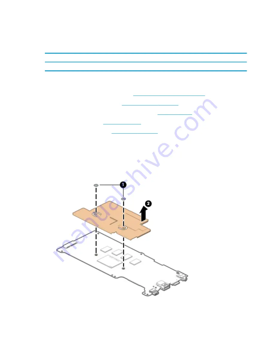
To remove the heat sink, use these procedures and illustrations.

Table 5-7

  Heat sink description and part number

Description

Spare part number

Heat sink (includes replacement thermal material)

928840-001

Before removing the heat sink, follow these steps:

1.

Prepare the computer for disassembly (see 

Preparation for disassembly on page 29

).

2.

Remove the top cover/keyboard (see 

Top cover/keyboard on page 29

).

3.

Disconnect the battery cable from the system board (see 

Battery on page 32

).

4.

Remove the speakers (see 

Speakers on page 34

).

5.

Remove the system board (see 

System board on page 37

).

Remove the heat sink:

1.

Turn the system board upside down with the front toward you.

2.

Remove the two Phillips M2.0×2.2 broad head screws (1) that secure the heat sink to the system board.

3.

Remove the heat sink (2).

ENWW

Component replacement procedures

39

Summary of Contents for Chromebook 11a

Page 1: ...Maintenance and Service Guide SUMMARY This guide provides information about spare parts removal and replacement of parts security backing up and more ...

Page 2: ...ements accompanying such products and services Nothing herein should be construed as constituting an additional warranty HP shall not be liable for technical or editorial errors or omissions contained herein First Edition March 2021 Document Part Number M52591 001 Product notice This guide describes features that are common to most models Some features may not be available on your computer To acce...

Page 3: ...the computer air vents Use the computer only on a hard flat surface Do not allow another hard surface such as an adjoining optional printer or a soft surface such as pillows or rugs or clothing to block airflow Also do not allow the AC adapter to come into contact with the skin or a soft surface such as pillows or rugs or clothing during operation The computer and the AC adapter comply with the us...

Page 4: ...iv Safety warning notice ENWW ...

Page 5: ...dures preliminary requirements 17 Tools required 17 Service considerations 18 Plastic parts 18 Cables and connectors 18 Drive handling 18 Electrostatic discharge information 19 Generating static electricity 19 Preventing electrostatic damage to equipment 20 Personal grounding methods and equipment 20 Grounding the work area 20 Recommended materials and equipment 21 Cleaning your computer 22 Enabli...

Page 6: ...ctor board cables 35 Connector board 35 System board 37 Heat sink 39 29 5 cm 11 6 in display assembly 40 6 Backing up resetting and recovering 49 Backing up 49 Resetting 49 Recovering 50 Installing the Chromebook Recovery Utility 50 Creating recovery media 50 Recovering the Chrome operating system 50 Setting up your computer after a reset or recovery 50 Erase and reformat the recovery media 50 7 S...

Page 7: ...cs card Intel HD Graphics 500 Memory On board nonupgradeable system memory supporting 8 GB Support for 3733 LPDDR4 1 1v IC FBGA200 system memory Media card reader microSD media reader slot Supports microSD SDHC SDXC Push push insertion removal On board nonupgradeable support for 32 GB v5 0 Networking Intel D1 7265 ac 2 2 Bluetooth 4 2 LE M 2 2230 non vPro PCI e USB WW with 2 antennas Storage On bo...

Page 8: ...nts Battery 2 cell 47 WHr HP Long Life Smart AC adapter 45 W non PFC standard USB Type C straight Power cord C5 1 0 m 3 3 ft Security Titan C security chip Nano security cable lock Operating system Google Chrome Serviceability End user replaceable part AC adapter 2 Chapter 1 Product description ENWW ...

Page 9: ...ck Connects optional powered stereo speakers headphones earbuds a headset or a television audio cable Also connects an optional headset microphone This jack does not support optional standalone microphones WARNING To reduce the risk of personal injury adjust the volume before putting on headphones earbuds or a headset For additional safety information see the Regulatory Safety and Environmental No...

Page 10: ... purchased separately when charging a small external device 4 AC adapter and battery light White The AC adapter is connected and the battery is fully charged Amber The AC adapter is connected and the battery is charging Off The battery is not charging 5 USB Type C power connector and port Connects an AC adapter that has a USB Type C connector supplying power to the computer and if needed charging ...

Page 11: ...t products charges small devices such as a smartphone when the computer is on or in Sleep mode NOTE Use a standard USB Type C charging cable or cable adapter purchased separately when charging a small external device and Connects a display device that has a USB Type C connector providing DisplayPort output 3 USB SuperSpeed port Connects a USB device provides high speed data transfer and for select...

Page 12: ...ll images NOTE Camera functions vary depending on the camera hardware and software installed on your product 4 Internal microphone Records sound The antennas are not visible from the outside of the computer For optimal transmission keep the areas immediately around the antennas free from obstructions For wireless regulatory notices see the section of the Regulatory Safety and Environmental Notices...

Page 13: ...mponent and description Component Description Touchpad zone Reads your finger gestures to move the pointer or activate items on the screen Power key Use the illustration and table to identify the power key ENWW Power key 7 ...

Page 14: ...ss of unsaved information If the computer has stopped responding and shutdown procedures are ineffective press and hold the power key for at least 10 seconds to turn off the computer Special keys Use the illustration and table to locate the special keys Table 2 6 Special keys and their descriptions Component Description 1 esc key Activates certain computer functions when pressed in combination wit...

Page 15: ...Table 2 7 Bottom component and description Components Description Speakers 2 Produce sound ENWW Bottom 9 ...

Page 16: ...10 Chapter 2 Components ENWW ...

Page 17: ...HP continually improves and changes product parts For complete and current information about supported parts for your computer go to http partsurfer hp com select your country or region and then follow the on screen instructions NOTE Details about your computer including model serial number product key and length of warranty are on the service tag at the bottom of your computer ENWW Computer major...

Page 18: ...ay spare parts are available as subcomponents not as whole units Display subcomponent spare parts are available For spare part information see 29 6 mm 11 6 in display assembly subcomponents on page 13 2 Top cover keyboard for use in the United States includes keyboard cable L92334 001 12 Chapter 3 Illustrated parts catalog ENWW ...

Page 19: ... number L14906 001 L14923 001 6b I O bracket L14359 001 6c Connector board low power cable included in the Cable Kit spare part number L14906 001 includes double sided adhesive 6c Connector board high power cable included in the Cable Kit spare part number L14906 001 includes double sided adhesive Intel D1 7265 ac 2 2 Bluetooth 4 2 LE M 2 2230 non vPro PCI e USB WW with 2 antennas not illustrated ...

Page 20: ...ncluded in the Cable Kit spare part number L14906 001 M54840 001 Webcam microphone module cable not illustrated included in the Cable Kit spare part number L14906 001 includes double sided adhesive 3 Display bracket L14913 001 4 29 6 cm 11 6 in HD BrightView LED UWVA touchscreen 220 nits display panel assembly M54841 001 5 Display panel cable L14915 001 6 Display hinges 2 includes left and right h...

Page 21: ...r non PFC 1 8 m 3 pin L43407 001 Cable Kit includes connector board high speed cable connector board low speed cable touchpad cable and webcam microphone module cable L14906 001 Power cord for use in North America C5 1 0 m conventional with sticker L19367 001 Rubber Kit includes microphone rubber and touchpad bracket rubber L20220 001 Screw Kit L14919 001 ENWW Miscellaneous parts 15 ...

Page 22: ...16 Chapter 3 Illustrated parts catalog ENWW ...

Page 23: ... properly prepare to disassemble and reassemble the computer Tools required You need the following tools to complete the removal and replacement procedures Forceps or tweezers Keyboard removal tool Magnetic Phillips P0 screwdriver Nonconductive nonmarking pry tool ENWW Tools required 17 ...

Page 24: ... when handling drives IMPORTANT Drives are fragile components Handle them with care To prevent damage to the computer damage to a drive or loss of information observe these precautions Before removing or inserting a hard drive shut down the computer If you are unsure whether the computer is off or in Hibernation turn the computer on and then shut it down through the operating system Before handlin...

Page 25: ...described Personal grounding methods and equipment on page 20 Avoid touching pins leads and circuitry Handle electronic components as little as possible If you remove a component place it in an electrostatic safe container Generating static electricity Follow these static electricity guidelines Different activities generate different amounts of static electricity Static electricity increases as hu...

Page 26: ...ound cords To provide proper ground a strap must be worn snug against bare skin The ground cord must be connected and fit snugly into the banana plug connector on the grounding mat or workstation Heel straps Toe straps Boot straps can be used at standing workstations and are compatible with most types of shoes or boots On conductive floors or dissipative floor mats use them on both feet with a max...

Page 27: ...nt static electricity Antistatic tape Antistatic smocks aprons or sleeve protectors Conductive bins and other assembly or soldering aids Conductive foam Conductive tabletop workstations with ground cord of 1 MΩ 10 resistance Static dissipative table or floor mats with hard tie to ground Field service kits Static awareness labels Wrist straps and footwear straps providing 1 MΩ 10 resistance Materia...

Page 28: ...commended steps to clean dirt and debris from your computer For computers with wood veneer see Caring for wood veneer select products only on page 24 1 Wear disposable gloves made of latex or nitrile gloves if you are latex sensitive when cleaning the surfaces 2 Turn off your device and unplug the power cord and other connected external devices Remove any installed batteries from items such as wir...

Page 29: ...ternal devices Remove any installed batteries from items such as wireless keyboards CAUTION To prevent electric shock or damage to components never clean a product while it is turned on or plugged in 3 Moisten a microfiber cloth with a mixture of 70 isopropyl alcohol and 30 water The cloth should be moist but not dripping wet CAUTION Do not use any of the following chemicals or any solutions that ...

Page 30: ...with a disinfectant See Cleaning your computer with a disinfectant on page 23 for sanitizing guidelines to help prevent the spread of harmful bacteria and viruses Packaging and transporting guidelines Follow these grounding guidelines when packaging and transporting equipment To avoid hand contact transport products in static safe tubes bags or boxes Protect ESD sensitive parts and assemblies with...

Page 31: ...lect BIOS event log and then select View BIOS Event Log or On consumer products Under the Main tab select System Log Post operating system failures are logged in the Event Viewer 1 Turn on the computer and allow the operating system to open 2 Click the search icon in the taskbar 3 Type Event Viewer and then press enter 4 Select the log from the left panel Details display in the right panel Chrome ...

Page 32: ...ces to display more options 3 Select Authorized service providers Component and diagnosis information failure detection and required action To locate diagnosis information and actions 1 Go to http www hp com go techcenter pcdiags 2 Select Get Support 3 Near the bottom of the window select Notebook PCs and the select your location 26 Chapter 4 Removal and replacement procedures preliminary requirem...

Page 33: ...vice provider parts IMPORTANT Components described in this chapter should be accessed only by an authorized service provider Accessing these parts can damage the computer or void the warranty NOTE Details about your computer including model serial number product key and length of warranty are on the service tag at the bottom of your computer ENWW 27 ...

Page 34: ...parts for your computer go to http partsurfer hp com select your country or region and then follow the on screen instructions You must remove replace or loosen as many as 44 screws when you service the parts described in this chapter Make special note of each screw size and location during removal and replacement 28 Chapter 5 Removal and replacement procedures for authorized service provider parts...

Page 35: ... 29 Remove the top cover keyboard 1 Turn the computer upside down with the front toward you 2 Remove the two Phillips M2 5 8 7 screws 1 that secure the bottom cover to the computer 3 Remove the six Phillips M2 5 6 6 screws 2 that secure the bottom cover to the computer 4 Turn the computer right side with the front toward you 5 Open the computer 6 Use a case utility tool 1 or similar thin plastic t...

Page 36: ...in the Cable Kit spare part number L14906 001 Before removing the touchpad cable follow these steps 1 Prepare the computer for disassembly see Preparation for disassembly on page 29 2 Remove the top cover keyboard see Top cover keyboard on page 29 Remove the touchpad cable 1 Detach the TouchPad cable 1 from the keyboard top cover The TouchPad cable is attached to the keyboard top cover with double...

Page 37: ...ble The touchpad bracket is included in the Bracket Kit spare part number L18300 001 The touchpad cable is included in the Cable Kit spare part number L14906 001 L14922 001 Before removing the touchpad follow these steps 1 Prepare the computer for disassembly see Preparation for disassembly on page 29 2 Remove the top cover keyboard see Top cover keyboard on page 29 Remove the touchpad 1 Release t...

Page 38: ...e this procedure to install the touchpad Battery To remove the touchpad cable use this procedure and illustration Table 5 3 Battery description and part number Description Spare part number Battery 2 cell 47 WHr 6 15 AHr Li ion includes cable 917725 855 Before removing the battery follow these steps 1 Prepare the computer for disassembly see Preparation for disassembly on page 29 2 Remove the top ...

Page 39: ... The battery connector tape is available using spare part number L14905 001 2 Disconnect the battery cable from the system board 2 3 Remove the two Phillips M2 0 4 1 screws 1 that secure the battery to the bottom cover 4 Remove the battery 2 ENWW Component replacement procedures 33 ...

Page 40: ...age 29 2 Remove the top cover keyboard see Top cover keyboard on page 29 3 Disconnect the battery cable from the system board see Battery on page 32 Remove the speakers 1 Disconnect the speaker cable 1 from the system board 2 Release the speaker cable 2 from the retention channel retention clips built into the bottom cover 3 Remove the three Phillips M2 0 4 1 screws 3 that secure the speakers to t...

Page 41: ...2 Remove the connector board cables 1 Release the two ZIF connectors 1 to which the USB port board cables are connected and then disconnect the USB port board cables from the system board 2 Release the two ZIF connectors 2 to which the USB port board cables are connected and then disconnect the USB port board cables from the USB port board 3 Detach the USB port board cables 3 from the bottom cover...

Page 42: ...he system board see Battery on page 32 Remove the connector board 1 Release the two ZIF connectors 1 to which the connector board cables are connected and then disconnect the connector board cables from the system board 2 Detach the connector board cables 2 from the bottom cover The connector board cables are attached to the bottom cover with double sided adhesive 3 Remove the Phillips M2 0 4 1 sc...

Page 43: ... 29 2 Remove the top cover keyboard see Top cover keyboard on page 29 3 Disconnect the battery cable from the system board see Battery on page 32 4 Remove the speakers see Speakers on page 34 NOTE When replacing the system board be sure to remove the heat sink see Heat sink on page 39 from the defective system board and install it on the replacement system board Remove the system board 1 Release t...

Page 44: ...ard bracket 2 The system board bracket is available using spare part number L14359 001 8 Lift the left edge of the system board 3 until it rests at an angle 9 Remove the system board 4 by sliding it up and to the left at an angle Reverse this procedure to install the system board 38 Chapter 5 Removal and replacement procedures for authorized service provider parts ENWW ...

Page 45: ...or disassembly on page 29 2 Remove the top cover keyboard see Top cover keyboard on page 29 3 Disconnect the battery cable from the system board see Battery on page 32 4 Remove the speakers see Speakers on page 34 5 Remove the system board see System board on page 37 Remove the heat sink 1 Turn the system board upside down with the front toward you 2 Remove the two Phillips M2 0 2 2 broad head scr...

Page 46: ...pare parts for displays are available only at the subcomponent level Before removing the display panel follow these steps 1 Prepare the computer for disassembly see Preparation for disassembly on page 29 2 Remove the top cover keyboard see Top cover keyboard on page 29 3 Disconnect the battery cable from the system board see Battery on page 32 4 Remove the speakers see Speakers on page 34 Remove t...

Page 47: ...it will open 8 If it is necessary to replace the display bezel or any of the display assembly subcomponents a Release the top edge of the display bezel 1 from the display assembly b Release the left and right edges of the display bezel 2 from the display assembly There is double sided adhesive 3 on the inside edge of the display bezel bottom edge Use caution when releasing the display bezel bottom...

Page 48: ...o replace the webcam microphone module a Remove the display bezel b Detach the webcam microphone module 1 from the display back cover The webcam microphone module is attached to the display back cover with double sided adhesive 42 Chapter 5 Removal and replacement procedures for authorized service provider parts ENWW ...

Page 49: ...re part number M54840 001 10 If it is necessary to replace the display panel a Remove the display bezel b Remove the six Phillips PM2 0 2 8 screws 1 that secure the display panel and display panel bracket to the display back cover c Remove the display panel bracket 2 The display panel bracket is available using spare part number xxx ENWW Component replacement procedures 43 ...

Page 50: ...upside down on the computer e Release the adhesive support strip 1 that secures the display panel cable connector to the display panel f Disconnect the display panel cable 2 from the display panel 44 Chapter 5 Removal and replacement procedures for authorized service provider parts ENWW ...

Page 51: ...rt number M54841 001 11 If it is necessary to replace the display back cover a Remove the display bezel b Remove the display panel c Remove the six Phillips PM2 0 2 9 broad head screws 1 that secure the back cover to the display hinges ENWW Component replacement procedures 45 ...

Page 52: ...2 If it is necessary to replace the display panel cable a Remove the display bezel b Remove the display panel c Remove the display back cover d Detach the display panel cable 1 from the display back cover The display panel cable is attached to the display back cover with double sided adhesive 46 Chapter 5 Removal and replacement procedures for authorized service provider parts ENWW ...

Page 53: ...part number L14915 001 and includes double sided adhesive 13 If it is necessary to replace the display hinges a Remove the display bezel b Remove the display panel c Remove the display back cover d Remove the four Phillips PM2 5 4 9 screws 1 that secure the hinges to the bottom cover e Release the hinges 2 by sliding them toward the inside of the computer ENWW Component replacement procedures 47 ...

Page 54: ...3 The display hinges are available using spare part number L14907 001 Reverse this procedure to reassemble and replace the display assembly 48 Chapter 5 Removal and replacement procedures for authorized service provider parts ENWW ...

Page 55: ...rive For detailed information about creating a backup go to http www support google com Resetting A factory reset erases all the information on your computer hard drive including all the files in the Downloads folder Before you reset make sure to back up your files to an optional USB flash drive SD memory card or through Google Drive The factory reset will not delete any of your files on Google Dr...

Page 56: ...ss the power button The computer restarts and the screen shows the Chrome OS is missing or damaged screen Installing the Chromebook Recovery Utility The Chromebook Recovery Utility is an app used to recover the original operating system and software programs that were installed at the factory This utility can be installed from the Chrome Web Store on any computer Creating recovery media Recovery m...

Page 57: ...ENWW Erase and reformat the recovery media 51 ...

Page 58: ...52 Chapter 6 Backing up resetting and recovering ENWW ...

Page 59: ...ion Table 7 1 Computer specifications Metric U S Temperature Operating 5 C to 35 C 41 F to 95 F Nonoperating 20 C to 60 C 4 F to 140 F Relative humidity noncondensing Operating 10 to 90 Nonoperating 5 to 95 Maximum altitude unpressurized Operating 15 m to 3 048 m 50 ft to 10 000 ft Nonoperating 15 m to 12 192 m 50 ft to 40 000 ft NOTE Applicable product safety standards specify thermal limits for ...

Page 60: ...54 Chapter 7 Specifications ENWW ...

Page 61: ...nd no more than 2 0 m 6 5 ft All power cord sets must be approved by an acceptable accredited agency responsible for evaluation in the country or region where the power cord set will be used The power cord sets must have a minimum current capacity of 10 A and a nominal voltage rating of 125 V ac or 250 V ac as required by the power system of each country or region The appliance coupler must meet t...

Page 62: ...IMKO 1 France UTE 1 Germany VDE 1 India BIS 1 Israel SII 1 Italy IMQ 1 Japan JIS 3 Netherlands KEMA 1 New Zealand SANZ 1 Norway NEMKO 1 People s Republic of China CCC 4 Saudi Arabia SASO 7 Singapore PSB 1 South Africa SABS 1 South Korea KTL 5 Sweden SEMKO 1 Switzerland SEV 1 Taiwan BSMI 6 Thailand TISI 1 United Kingdom ASTA 1 56 Chapter 8 Power cord set requirements ENWW ...

Page 63: ... conductor 0 75 mm or 1 25 mm conductor size The wall plug must be a two pole grounding type with a Japanese Industrial Standard C8303 7 A 125 V ac configuration 4 The flexible cord must be Type RVV three conductor 0 75 mm conductor size Power cord set fittings appliance coupler and wall plug must bear the CCC certification mark 5 The flexible cord must be Type H05VV F three conductor 0 75 mm cond...

Page 64: ...58 Chapter 8 Power cord set requirements ENWW ...

Page 65: ...battery in general household waste Follow the local laws and regulations in your area for battery disposal HP encourages customers to recycle used electronic hardware HP original print cartridges and rechargeable batteries For more information about recycling programs see the HP website at http www hp com recycle ENWW 59 ...

Page 66: ...60 Chapter 9 Recycling ENWW ...

Page 67: ...spare part number 35 creating recovery media 50 D display specifications 53 display assembly removal 40 display panel removal 43 spare part number 45 display panel cable removal 46 spare part number 47 E electrostatic discharge ESD 17 19 preventing damage 17 19 20 erase and reformat recovery media removal 50 esc key identifying 8 F factory reset 49 G grounding methods 17 19 20 guidelines packaging...

Page 68: ...art number 15 S Screw Kit spare part number 15 setting up computer after reset or recovery 50 speaker removal 34 spare part number 34 speakers identifying 9 specifications computer 53 display 53 hard drive 53 static electricity 17 19 support information 24 system board removal 37 spare part number 37 T top cover keyboard removal 29 spare part number 29 touchpad removal 31 spare part number 31 touc...

Reviews: