background image

Maintenance

Operator protection from electric shock hazard is provided by a double insulated enclosure.
Refer to pages 1-4 and 1-5 for maximum voltage specifications.  When servicing, use only
specified replacement parts.

Battery Replacement

Replace the battery when the symbol appears in the display or before calibration. Replace
both batteries at the same time. Use high-quality type AA alkaline (IEC LR6) batteries.
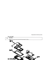
Remove the batteries if the multimeter is to be stored for extended periods of time. Refer to
the disassembly drawing on page 6-5.

Fuse Replacement

Fuse locations are shown in the diagram on page 6-5.  Fuses are listed in the replaceable
part list on page 6-4. See fuse check procedure in Troubleshooting table below.

CAUTION

For continued protection use only the specified manufacturer part number or HP part number
fuse for replacement purposes. 

1-15

Summary of Contents for 971A

Page 1: ...ill find any other available product information on the Agilent Test Measurement website www tm agilent com HP References in this Manual This manual may contain references to HP or Hewlett Packard Please note that Hewlett Packard s former test and measurement semiconductor products and chemical analysis businesses are now part of Agilent Technologies We have made no changes to this manual copy In ...

Page 2: ...HP 971A Multimeter User s Guide Part Number 00971 90002 March 1995 ...

Page 3: ......

Page 4: ... and Adjustment 1 14 Required Test Equipment 1 14 Calibration Procedure 1 14 Maintenance 1 15 Battery Replacement 1 15 Fuse Replacement 1 15 Troubleshooting 1 16 Cleaning 1 16 Replaceable Parts Accessories 1 16 Specifications 1 17 General 1 17 DC Voltage 1 17 AC Voltage 1 18 DC Current 1 18 AC Current 1 19 Resistance 1 19 Continuity 1 19 Diode 1 20 Temperature 1 20 Frequency 1 20 Adjustments 6 1 C...

Page 5: ...on when using the current function do not leave one probe connected to the circuit under test and the other probe disconnected exposed and readily accessible touchable Safety Symbols Indicates the operator must refer to an explanation in this manual Indicates terminals at which dangerous voltages may exist WARNING TO AVOID ELECTRICAL SHOCK or damage to the multimeter do not apply more than 1000 Vd...

Page 6: ...oltage Limitations AC and DC Voltage Functions 1000V MAX indicates the maximum voltage between input terminals and earth is 1000 V dc or ac rms Do not use the multimeter on any ACV circuit where the maximum impulse overvoltage may be more than 4000Vpk or any DCV circuit where the maximum impulse overvoltage may be more than 2500Vpk between the COM and VOLT terminals Excessive impulse overvoltage c...

Page 7: ... leads whose insulation has cuts cracks or other damage that may result in reduced electric shock protection 2 Keep insulation surface clean between the probe tip connector and the finger guards 3 If probes other than the ones specified are to be used with the multimeter be sure the probes and their leads are rated for the voltage and current to which they will be subjected Do not exceed the volta...

Page 8: ...ltage Diode Resistance Frequency Temperature and Continuity Measurements SAFETY SHUTTER Slide up to open shutters for current measurement inputs Must have the function switch in one of the Current Measurement positions to open shutter Close shutter to change function switch to any other measurement function ...

Page 9: ...A to 0 4 A AC Current 10 µA to 0 4 A µA DC Current 0 1 µA to 4 mA AC Current 0 1 µA to 4 mA Diode Test 0 to 2 V Auto Diode Test 0 to 2 V Ω Resistance 0 1 Ω to 40 MΩ Continuity alarm at 20 Ω Temperature in F 112 F to 302 F Temperature in C 80 C to 150 C Hz Frequency 5 Hz to 99 9 kHz mV DC volts AC volts Operation ...

Page 10: ...change any function to cancel Defeat by holding the key for 2 seconds while applying power Relative Percent Press Action Main Display Secondary Display Makes the last displayed measurement the reference Each measured value relative to the reference value difference Range Calculates the percentage change from the reference Each measured value as a percent change of the reference value Range Cancels...

Page 11: ...ximum values Each measured value Elapsed time Press and hold 1 second to cancel 1 Automatic power off and auto ranging are disabled when Min Max is selected Bargraph will indicate and hold maximum values 2 Time is recorded and displayed in minutes up to the maximum recording time of 1999 minutes Recording will stop at the maximum time 3 The H annunciator is displayed when Min Max recording is paus...

Page 12: ...ring circuit will display and hold the last stable reading Range Press Action Main Display Secondary Display Changes from auto ranging to manual ranging Measurement value Range Change manual range UP once with each keypress 1 Measurement value Range Returns to auto ranging when key is held for 1 second Measurement value Range 1 When upper range is reached the sequence begins again at the lowest ra...

Page 13: ... Hold4 Auto Hold Range µA mA 10A Ω 1 F C2 Hz2 3 mV mV V V 1 Invokes zero adjust when display is less than 9 9 Ω 2 Bargraph not available 3 Changes input attenuator frequency is always auto range 4 Bargraph updates with input value 5 Secondary display shows elapsed time in minutes Operation ...

Page 14: ... function selected Indicates an overload condition at the measurement terminals Continuous tone Indicates a resistance of 20 Ω when using the Continuity function Low Battery indicator Replace batteries when on Secondary Display Shows Range most functions Elapsed time Min Max Main Display Annunciators shown inside front cover Number of digits is set by range and function Displays O L to indicate an...

Page 15: ...nstall new batteries described below and close the cover Turn the multimeter on and allow a 30 minute warm up Open the case 3 Set the multimeter function and range and the source output to the values specified at each step in the calibration table on page 6 2 4 When appropriate make the adjustments indicated in the calibration table to bring the multimeter display within the limits CAUTION Dangero...

Page 16: ...e both batteries at the same time Use high quality type AA alkaline IEC LR6 batteries Remove the batteries if the multimeter is to be stored for extended periods of time Refer to the disassembly drawing on page 6 5 Fuse Replacement Fuse locations are shown in the diagram on page 6 5 Fuses are listed in the replaceable part list on page 6 4 See fuse check procedure in Troubleshooting table below CA...

Page 17: ...nge test leads or function switch position Battery Annunciator on Low battery voltage Replace batteries Unable to measure current 10 A or mA µA Open input protection fuse Check fuse Connect test lead between V input terminal and 10A or 10 mA µA terminal Select 10A or 10mA range unit will rapidly beep if fuse is OK Replace fuse if no beep Cleaning Wipe instrument with a soft rag dampened with soap ...

Page 18: ... RH max 40 C to 50 C 70 RH max no condensation Storage Temperature 25 to 60 C 70 RH max no condensation Display reading rate Approximately 2 3 times second Frequency 1 second Bargraph reading rate Approximately 23 times second Battery life Approximately 1000 hours DC Voltage Range Resolution Accuracy Input Resistance 400 mV 100 µV 0 3 1 10 MΩ 4 0 V 1 mV 11 MΩ nominal 40 V 10 mV 10 MΩ nominal 400 V...

Page 19: ... 1 mV 11 MΩ 50 pF 40 V 10 mV 10 MΩ 50 pF 400 V 100 mV 1000 V 1 V Not Specified Common Mode Rejection Ratio CMR 1 kΩ imbalance 60 dB DC to 60 Hz Response time 2 seconds maximum DC Current Range Resolution Accuracy Input Resistance Maximum Input 400 µA 100 nA 0 5 2 550 Ω 0 5 A fused 4000 µA 1 µA 1 2 40 mA 10 µA 8 Ω 400 mA 100 µA 1 2 2 10 A 10 mA 0 05 Ω 15 A fused Specifications ...

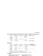
Page 20: ...curacy Test Current Maximum Open Circuit Voltage 400 Ω 100 mΩ 0 5 1 1 0 8 mA 3 2 V 4 0 kΩ 1 Ω 0 5 1 80 µA 1 1 V 40 kΩ 10 Ω 10 µA 400 kΩ 100 Ω 1 1 µA 4 0 MΩ 1 kΩ 110 nA 40 MΩ 10 kΩ 1 0 1 1 After zero adjust of input leads Zero adjust range up to 9 9 Ω Response time 400 Ω to 400 kΩ 2 seconds 10 MΩ to 40 MΩ 10 seconds Continuity Measurement Current 0 8 mA maximum Open circuit voltage 3 2 Vpeak Displa...

Page 21: ...on 0 1 0 2 Accuracy 1 0 5 1 0 1 Accuracy does not include 5 kΩ Thermistor error Frequency AC Coupled Frequency Range Resolution Accuracy Maximum Input 5 Hz to 9999 Hz 1 Hz 0 02 1 660 Vrms 9 0 kHz to 99 9 kHz 10 Hz 100 Vrms Input Attenuator Input Voltage Input Impedance 5 Hz to 10 kHz 10 kHz to 100 kHz 4 100 mV to 4 V rms 800 mV to 4 V rms 2 3 MΩ 50 pF 40 4 V to 40 V rms 4 V to 40 V rms 1 3 MΩ 50 p...

Page 22: ...Adjustments ...

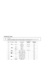
Page 23: ...al Adjustment limits Tolerance counts 1 mV 400 mV Short 1 2 380 0 mV RV1 1 12 3 380 0 mV 12 4 V 4 V 3 800 V RV2 1 12 5 40 V 38 00 V 12 6 400 V 380 0 V 12 7 1000 V 1000 V 4 8 V 400 V 380 0 V 100 Hz RV3 1 40 9 380 0 V 1 kHz 61 10 mV 400 mV 380 0 mV 100 Hz 40 11 380 0 mV 1 kHz 61 12 V 4 V 3 800 V 100 Hz 40 13 3 800 V 1 kHz 61 14 40 V 38 00 V 100 Hz 40 15 38 00 V 1 kHz 61 16 1000 V 1000 V 100 Hz 12 17...

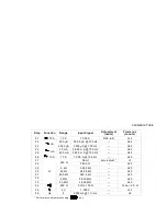
Page 24: ... 40 mA 38 00 mA 100 Hz 62 25 400 mA 380 0 mA 100 Hz 62 26 10 A 10 A 10 00 A 100 Hz 20 27 Ω 400 Ω Short zero adjust 1 1 28 380 0 Ω 20 29 4 kΩ 3 800 kΩ 20 30 40 kΩ 38 00 kΩ 20 31 400 kΩ 380 0 kΩ 20 32 4 MΩ 3 800 MΩ 20 33 40 MΩ 38 00 MΩ 40 34 400 Ω 0 Ω to 100 Ω Tone 20 Ω 35 2 V 1 000 V 12 36 Hz 4 9000 Hz 1 Vrms 2 1 Perform zero adjustment using key Calibration Table ...

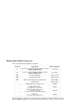
Page 25: ...P2 Dust moisture seal 00971 64403 MP3 Bottom case assembly includes stand 00971 64402 Rubber Boot 00971 86001 Replacement Test Leads 2 pair E2305A Temperature probe 5 KΩ 25 C Thermistor E2308A Surface temperature sensor Thermistor 0 1 C 12 lead requires dual banana plug 40653B Soft Case fits meter with rubber boot E2304A Operator protection from electric shock hazard is provided by a double insula...

Page 26: ...Disassembly WARNING Always disconnect the test leads before opening the case Replaceable Parts Accessories ...

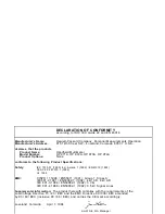
Page 27: ...ing Product Specifications Safety IEC 1010 01 1990 Incl Amend 1 1992 EN61010 1993 CSA C22 2 1010 1 1992 UL 1244 EMC CISPR 11 1990 EN55011 1991 Group 1 Class A IEC801 2 1991 EN50082 1 1992 4 kV CD 8 kV AD IEC 801 3 1984 EN50082 1 1992 3 V m IEC 801 4 1988 EN50082 1 1992 0 5 kV Signal Lines Supplemental Information The product herewith complies with the requirements of the Low Voltage Directive 73 2...

Page 28: ... No other express warranty is given The repair or replacement of a product is your exclusive remedy ANY OTHER IMPLIED WARRANTY OF MERCHANTABILITY OR FITNESS IS LIMITED TO THE THREE YEAR DURATION OF THIS WRITTEN WARRANTY Some states provinces or countries do not allow the exclusion or limitation or incidental or consequential damages so the above limitation or exclusion may not apply to you The war...

Reviews: