


Chapter 6
Troubleshooting and Installation-Related Tasks
Installing a Core I/O Card
119
Installing a Core I/O Card
The Core I/O card for Superdome Precision Architecture-Reduced Instruction Set Computing (PA-RISC)
servers is an HP-designed multi-function (1x) Peripheral Component Interconnect (PCI) card containing a
10/100Base-T LAN (device 1) and three RS-232 serial ports (device 0). One of the three serial ports is required
by every partition in order to communicate using console functions, in conjunction with the Guardian Service
Processor (GSP), via the sideband connector. Like the I/O subsystem, the Core I/O card is a mandatory
component for bringing up a partition.
To install the Core I/O card, DC power to the card cage must be turned off. Refer to “Installing a PCI I/O Card
While the Cell is Off ” on page 120.
Locating the Core I/O Slot
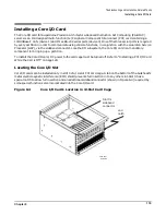
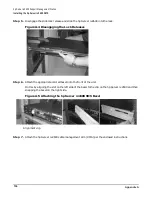
Core I/O cards can be installed only in slot 0 of a 12-slot PCI card cage. A tab on the bottom of the bulkhead’s
metal electromagnetic interference (EMI) shield prevents full insertion into any other slot. Slot 0 has a
special notch to allow full insertion and an additional sideband connector (shown in Figure 6-4) required by
some special functions also incorporated into the Core I/O card.
Figure 6-4
Core I/O Card’s Location in 12-Slot Card Cage
60IO700c
04/06/00
Slot 0’s
sideband
connector
and
notch
Summary of Contents for 9000 Superdome
Page 8: ...Contents 8 ...
Page 9: ...9 Preface ...
Page 21: ...21 IEC 60417 IEC 335 1 ISO 3864 IEC 617 2 International Symbols ...
Page 22: ...22 Figure 9 Superdome Declaration of Conformity Page 1 ...
Page 23: ...23 Figure 10 Superdome Declaration of Conformity Page 2 ...
Page 24: ...24 ...
Page 32: ...Chapter 1 Introduction Installation Warranty 8 ...
Page 130: ...Chapter 4 Verifying and Booting Superdome Enabling iCOD 106 ...
Page 172: ...Appendix A hp Server rx2600 Support Management Station Configuring the SMS 148 ...
Page 184: ...Appendix C Superdome LAN Interconnect Diagram 160 ...
Page 193: ...Appendix F 169 F A180 Support Management Station ...
Page 230: ...Appendix G Connecting Multiple SPU Cabinets Connecting Cables 206 ...
Page 256: ...Appendix H JUST Exploration Tool Error Conditions 232 ...