background image

Installing the System

Installing Additional Components

Chapter 1

58

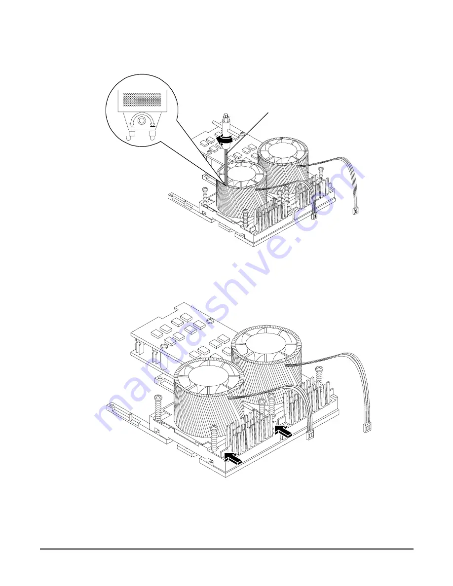
Figure 1-44 Locking the Dual Processor Module in Place

Step 9.

Slide the sequencing retainer plate toward the front of the server.

Figure 1-45 Slide the Sequencing Retainer Plate

Step 10.

Screw in the four heatsink captive screws in a criss-cross torquing pattern by alternately 
tightening the screws so as not to completely tighten one screw before the others.

CPU Install Tool
(2.5 mm Driver/Allen 
Wrench)

Summary of Contents for 9000 rp3410

Page 1: ...Installation Guide HP 9000 rp3410 and HP 9000 rp3440 Manufacturing Part Number A7137 96007 Seventh Edition April 2007 Printed in the US ...

Page 2: ...s accompanying such products and services Nothing herein should be construed as constituting an additional warranty HP shall not be liable for technical or editorial errors or omissions contained herein Printed in U S A Intel Pentium Intel Inside Itanium and the Intel Inside logo are trademarks or registered trademarks of Intel Corporation or its subsidiaries in the United States and other countri...

Page 3: ...d Disk Drives 35 Installing a DVD Drive 39 Removing and Replacing Airflow Guides 40 Installing Additional System Memory 46 Removing and Replacing the PCI Card Cage 50 Installing PCI Cards 52 Installing an Additional Power Supply 54 Installing an Additional Processor Module 55 Replacing the System Battery 64 Installing the Server Into a Rack Non HP Rack or Pedestal 66 HP Rack 66 Non HP Rack 66 Pede...

Page 4: ...g System 82 Booting and Shutting Down HP UX 82 Verifying the Server Configuration Using Boot Console Handler 84 Troubleshooting 85 Troubleshooting Methodology 85 Troubleshooting Using the Server Power Button 85 Server Does Not Power On 86 Operating System Does Not Boot 86 Operating System Boots with Problems 87 Intermittent Server Problems 87 DVD Problems 87 Hard Drive Problems 87 Console Problems...

Page 5: ...ble 1 7 Setup Checklist 69 Table 1 8 Console Connection Matrix 71 Table 1 9 LAN Configuration Methods 71 Table 1 10 ARP Ping Commands 73 Table 1 11 Power States 80 Table 1 12 Server Power Button Functions When Server is On and at BCH 85 Table 1 13 Server Power Button Functions When Server is On and OS is Running 86 Table 1 14 Server Power Button Functions When Server is Off 86 Table 1 15 Control P...

Page 6: ...Tables 6 ...

Page 7: ...he Side Cover on a Pedestal Mounted Server 33 Figure 1 21 Removing the Front Bezel on a Pedestal Mounted Server 34 Figure 1 22 Aligning the Pedestal Front Bezel 35 Figure 1 23 Front View of the HP 9000 rp3410 rp3440 Server 36 Figure 1 24 Filler Removal from Slot 1 37 Figure 1 25 Disk Drive Installation in Slot 3 37 Figure 1 26 Hard Drive Lock 38 Figure 1 27 DVD Drive Installation 39 Figure 1 28 Ai...

Page 8: ... Module Power Pod 60 Figure 1 49 Install the Processor Module Power Pod Mounting Screws 61 Figure 1 50 Connecting the Power Pod Cable 62 Figure 1 51 Routing the Turbofan Power Cables through Heatsink Posts 63 Figure 1 52 Replacing the System Battery 65 Figure 1 53 LAN Ports on Server Rear 68 Figure 1 54 iLO MP Setup Flowchart 70 Figure 1 55 Web Login Page 78 Figure 1 56 Status Summary Page 79 Figu...

Page 9: ...s document can be found on the Web at http www docs hp com Intended Audience This document is intended to provide technical product and support information for authorized service providers system administrators and HP support personnel This document is not a tutorial New and Changed Information in This Edition This following changes are included in this edition Updated formatting throughout the gu...

Page 10: ...e Section 8 Powering On the Server Provides instructions on how to power on the server Section 9 Booting the Operating System Provides instructions on how to boot the operating system Section 10 Troubleshooting Diagnostics and basic troubleshooting information Typographic Conventions This document uses the following conventions WARNING A warning lists requirements that you must meet to avoid perso...

Page 11: ...re optional in formats and command descriptions If the contents are a list separated by you must select one of the items The contents are required in formats and command descriptions If the contents are a list separated by you must select one of the items The preceding element may be repeated an arbitrary number of times Separates items in a list of choices HP UX Release Name and Release Identifie...

Page 12: ...rrently publishes such as HP UX books including HP UX 11i System Administration Handbook http www hp com hpbooks prentice ptr_0130600814 html HP UX Virtual Partitions http www hp com hpbooks prentice ptr_0130352128 html HP Books are available worldwide through bookstores online booksellers and office and computer stores HP Encourages Your Comments HP encourages your comments concerning this docume...

Page 13: ... and Powering OFF on page 80 Booting the Operating System on page 82 Troubleshooting on page 85 Introduction The HP 9000 rp3410 server is a 1P 1C 1P 2C rack or pedestal mount server Similarly the HP 9000 rp3440 server is a 1P 1C 1P 2C or 2P 2C rack or pedestal mount server Both of these servers are based on the PA RISC processor family architecture The server accommodates up to 12 DIMMs and intern...

Page 14: ... Figure 1 3 and Figure 1 4 show the front rear and pedestal mount views of the HP 9000 rp3410 and rp3440 servers Figure 1 1 HP 9000 rp3410 rp3440 Server Front View Figure 1 2 HP 9000 rp3410 rp3440 Server Front View with Bezel Removed Figure 1 3 HP 9000 rp3410 rp3440 Server Rear View ...

Page 15: ...Installing the System Introduction Chapter 1 15 Figure 1 4 HP 9000 rp3410 rp3440 Server Pedestal Mount ...

Page 16: ... SCSI Hot Plug Disk or Three 146 GB 10K RPM Ultra320 SCSI Hot Plug Disk Video A6150B PCI card optional A6150B PCI card optional SCSI N A Integrated Ultra 3 SCSI dual channel controller 80 MBs transfer rate with one internal 68 pin connector and one external 68 pin connector LAN PCI Gigabit fast ethernet controller PCI Gigabit fast ethernet controller PCI Slots Two 64 bit hot pluggable PCI X slots ...

Page 17: ...mmon shared memory The Integrity iLO MP interprets and stores event IDs Reviewing these events helps you diagnose and troubleshoot problems with the server Dimensions and Values Table 1 2 lists the dimensions and their values of the HP 9000 rp3410 and rp3440 servers Safety Information Use care to prevent injury and equipment damage when performing removal and replacement procedures Voltages might ...

Page 18: ...even when the main power switch is turned off Failure to observe this warning can result in personal injury or damage to equipment Do not wear loose clothing that can snag or catch on the server or on other items Do not wear clothing subject to static charge build up such as wool or synthetic materials If installing an internal assembly wear an antistatic wrist strap and use a grounding mat such a...

Page 19: ...drive status LED is not used on the HP 9000 rp3410 or HP 9000 rp3440 server Activity LED The Drive Activity LED is flashing green and indicates disk drive activity This LED is directly controlled by the disk drive and turns on when a drive is accessed Figure 1 7 Hard Disk Drive LED Indicators Table 1 3 lists the hard disk drive LED definitions Table 1 3 Hard Disk Drive LED Definitions LED Activity...

Page 20: ...rive LED definitions Rear Panel The rear panel of the HP 9000 rp3410 and rp3440 servers includes communication ports I O ports ac power connector and the locator LED button Additional LEDs located on the rear panel of the HP 9000 rp3410 and rp3440 servers signal the operational status of 10 100 1000 Base T Ethernet LAN iLO MP card LAN Figure 1 9 shows the rear panel ports and LEDs Table 1 4 DVD Dr...

Page 21: ...and LED The locator button and LED are used to help locate a server within a rack of servers When the button is engaged the blue LED illuminates and an additional blue LED on the front panel of the server illuminates You can remotely activate this function Video not used 15 pin female video connector DISABLED DO NOT USE To enable video capability you must obtain the supported A6150 video PCI card ...

Page 22: ...her LAN information and determine the two separate IP addresses for the iLO MP LAN and the system LAN Step 2 Establish a method to connect to the server console Step 3 Verify electrical requirements and ensure that grounding specifications and power requirements have been met Step 4 Validate server physical space requirements Step 5 Confirm environmental requirements Table 1 6 Installation Sequenc...

Page 23: ...emove all inner accessory cartons and the top foam cushions leaving only the server IMPORTANT Inspect each carton for shipping damage as you unpack the server Checking the Inventory The sales order packing slip lists all of the equipment shipped from HP Use this packing slip to verify that all of the equipment has arrived NOTE To identify each item by part number see the sales order packing slip R...

Page 24: ...quired to elevate the server and enable the forks of the lifter to be placed under the server Step 4 Insert the lifter forks under the server Step 5 Carefully roll the lifters forward until it is fully against the side of the server Step 6 Slowly raise the server off the pallet until it clears the pallet cushions Step 7 Carefully roll the lifter and server away from the pallet Do not raise the ser...

Page 25: ...p cover Accessing a Rack Mounted Server HP 9000 rp3410 and rp3440 servers are designed to be rack mounted The following procedure explains how to gain access to a server that is mounted in an approved rack For slide installation instructions see the Installation Guide Mid Weight Slide Kit HP part number 5065 7291 This document can be accessed on the Web at http www hp com racksolutions WARNING Ens...

Page 26: ... latches are closed Removing and Replacing the Top Cover on a Rack Mounted Server Removal of this cover is necessary when installing or removing many components Removing the Top Cover on a Rack Mounted Server NOTE If you are replacing a hot swappable item you can leave the server on and external cables including the power cord connected Step 1 Power off the server and disconnect the power and exte...

Page 27: ...he server chassis Replacing the Top Cover on a Rack Mounted Server CAUTION Secure any wires or cables in the server so they will not get cut or interfere with the replacement of the cover Step 1 Align the front edge of the cover with the alignment mark on the optical drive bay Figure 1 12 Aligning the Top Cover To replace cover align front edge here then slide forward ...

Page 28: ... 3 Slide the server into the rack enclosure and reconnect the power and external cables Removing and Replacing the Front Bezel on a Rack Mounted Server You must remove the front bezel from the chassis to gain access to the power supplies and optical drive Removing the Front Bezel on a Rack Mounted Server Step 1 Press in on the retaining clips located on the right side of the front panel Figure 1 1...

Page 29: ... of the server until it locks into place Figure 1 15 Replacing the Front Bezel Accessing a Pedestal Mounted Server NOTE If you are replacing a hot swappable item you can leave the server on and external cables including the power cord connected Removing the Side Cover on a Pedestal Mounted Server Step 1 Power off the server and disconnect the power and external cables Step 2 Remove the side cover ...

Page 30: ...stal Mounted Server Removing the Top Cover on Pedestal Mounted Server To remove the top cover follow these steps Step 1 Turn the top cover lock keyswitch to the unlocked position Step 2 Rotate the blue release handle to release the latch Step 3 Slide the cover toward the back of the chassis and lift the cover off ...

Page 31: ...per cooling of internal components Operating the server with the cover removed can cause the server to quickly overheat Replacing the Top Cover on a Pedestal Mounted Server CAUTION Secure any wires or cables in the server so they do not get cut or interfere with the replacement of the cover To replace the top cover follow these steps Step 1 Align the front edge of the top cover with the alignment ...

Page 32: ... front of the server until the blue release lever snaps in place Figure 1 19 Replacing the Top Cover on a Pedestal Mounted Server Replacing the Side Cover on a Pedestal Mounted Server To replace the side cover follow these steps Step 1 Align the cover s mounting holes with the matching tabs on the server chassis To replace cover align front edge here then slide forward ...

Page 33: ...s Removing and Replacing Front Bezel on a Pedestal Mounted Server You must remove the front bezel from the chassis to gain access to the power supplies and optical drive Removing the Front Bezel on a Pedestal Mounted Server To remove the front bezel parts follow these steps Step 1 Use the indentation at the top edge of the bezel to pull the bezel away from the chassis and to a 45 degree angle ...

Page 34: ...el off the mounting tabs and away from the chassis Replacing the Front Bezel on a Pedestal Mounted Server To replace the front bezel parts follow these steps Step 1 Position the bezel at an approximate 45 degree angle and align the retaining slots at the bottom with the retaining tabs on the chassis Press the bezel against the chassis to engage the tabs ...

Page 35: ...stalling additional internal hard disk drives CAUTION A hot pluggable device can require interaction with the operating server before the device can be safely installed into the server Verify that the operating system supports installing disk drives while the operating system is running If the operating system does not support this feature shut down the operating system before attempting this proc...

Page 36: ... steps Step 1 If you will be locking the hard drive in place you must remove the cover to access the hard drive lock Proceed as follows a If rack mounted slide the server out from the rack until it stops See Extend the Server from the Rack on page 25 b Remove the cover and bezel See Removing and Replacing Server Covers and Bezels on page 25 Step 2 Remove the slot filler that is installed in the sl...

Page 37: ...Figure 1 24 Filler Removal from Slot 1 Step 3 Slide the hard disk drive into the slot until it is seated Figure 1 25 Disk Drive Installation in Slot 3 Step 4 Close the drive ejector handle by pushing it down until it clicks Step 5 If desired lock the hard drive in place ...

Page 38: ...ive installation by using the system utilities Use the iLO MP commands to verify operation Use the BCH commands to verify operation Use diagnostics provided by the offline diagnostic environment to exercise the module added Step 7 If rack mounted slide the server back into the rack until it stops Step 8 Check the installation of the hard disk drive by powering on the server and checking the virtua...

Page 39: ...ower source is connected This voltage is present even when the main power switch is in the off position Failure to observe this warning can result in personal injury or damage to equipment CAUTION Observe all ESD safety precautions before attempting this procedure Failure to follow ESD safety precautions can result in damage to the server Failure to properly complete the steps in this procedure wi...

Page 40: ...Reconnect the power and external cables and turn on the server Step 8 Verify the drive operation by using the system utilities Use the iLO MP commands to verify operation Use the BCH commands to verify operation Use diagnostics provided by the offline diagnostic environment to exercise the newly installed module Removing and Replacing Airflow Guides You must remove airflow guides before installing...

Page 41: ...e Step 1 Power off the server and disconnect power and external cables Step 2 Remove the server chassis cover See Removing and Replacing the Top Cover on a Rack Mounted Server on page 26 Step 3 Grasp the memory airflow guide and lift it out of the server Figure 1 29 Removing the Memory Airflow Guide Processor Airflow Guide Memory Airflow Guide Front Portion of Processor Airflow Guide ...

Page 42: ... Processor Airflow Guide Step 1 Power off the server disconnect power and external cables Step 2 Remove the server cover See Removing and Replacing the Top Cover on a Rack Mounted Server on page 26 Step 3 Remove the IDE cable and power module cables from the processor airflow guide cable clips Step 4 Remove the main portion of the airflow guide a Hold the guide using the opening on top of the guid...

Page 43: ...er 1 43 Figure 1 31 Removing Fans 1A and 1B Step 6 Grasp system fan 1B and lift it from its socket Figure 1 31 Step 7 Remove the memory airflow guide Removing the Memory Airflow Guide on page 41 Step 8 Rotate the clip clockwise to release the latch Fan 1A Fan 1B ...

Page 44: ...1 32 Open the Release Clip Step 9 Disconnect the power cable connected to the guide from the system board by squeezing the clips Step 10 Lift the front portion of the processor airflow guide out of the server Figure 1 33 Remove the Front Portion of the Processor Airflow Guide ...

Page 45: ...igure 1 34 CAUTION Turbo fan power cables can be damaged if pinched between the heatsink posts and the processor airflow guide Ensure that the cables are below the top surface of the heatsink posts before installing the processor airflow guide Figure 1 34 Routing the Turbofan Power Cables through Heatsink Posts Step 4 Replace the main portion of the airflow guide a Hold the opening on top of the p...

Page 46: ...en the main power switch is in the off position Failure to observe this warning can result in personal injury or damage to equipment CAUTION Observe all ESD safety precautions before attempting this procedure Failure to follow ESD safety precautions can result in damage to the server Supported DIMM Sizes Supported DIMM sizes are as follows 256 MB 512 MB 1 GB 2 GB 4 GB HP 9000 rp3440 only If 4 GB D...

Page 47: ...of four This allows memory configurations of two four eight or twelve DIMMs In the current server model A7136B memory must be installed as quads groups of four This allows memory configurations of four eight or twelve DIMMs Thus the HP 9000 rp3410 server must include a minimum of 512 MB model A7136A or 1 GB model A7136B and can include up to six GB of memory in combinations of 256 MB 512 MB and 1 ...

Page 48: ...installed as quads groups of four This allows memory configurations of four eight or twelve DIMMs Thus the HP 9000 rp3440 server must include a minimum of 1 GB and can include up to 24 GB of memory in combinations of 256 MB 512 MB 1 GB and 2 GB DIMMs or 32 GB of memory consisting of eight 4 GB DIMMs Different size DIMMs can be installed in the server except when 4 GB DIMMs are used but all four DI...

Page 49: ...he server cover See Removing and Replacing Server Covers and Bezels on page 25 Step 3 Remove the memory airflow guide See Removing the Memory Airflow Guide on page 41 CAUTION To ensure that memory modules are not damaged during removal or installation power off the server and unplug the power cord from the ac power outlet Wait until the LED on the back of the power supply turns off before removing...

Page 50: ...ilities Use the iLO MP commands to verify operation Use the BCH commands to verify operation Use diagnostics provided by the offline diagnostic environment ODE to exercise the memory added Removing and Replacing the PCI Card Cage Accessory cards are installed in a removable PCI card cage This section explains how to remove and replace the PCI card cage Removal is required to install accessory card...

Page 51: ...ift up on the PCI card cage release lever and the back edge of the PCI card cage and lift the PCI card cage out of the server Figure 1 37 Removing the PCI Card Cage Step 4 Grasp the PCI card cage cover and slide it away from the bulkhead end of the cage then lift the cover off ...

Page 52: ...er the card cage into the server chassis Step 4 Press the PCI card cage release lever into the lowered position to lock the card cage into the server chassis Installing PCI Cards The server can contain up to 4 PCI cards PCI cards are located in the PCI card cage The HP 9000 rp3410 server provides two 64 bit 133 MHz PCI X card sockets as slots 1 and 2 The HP 9000 rp3440 server provides four 64 bit ...

Page 53: ... card cage See the labels on the rear panel of the chassis for correct PCI slot number identification Installing a PCI Card Step 1 Remove the cover See Removing and Replacing the Top Cover on a Rack Mounted Server on page 26 Step 2 Remove the PCI cage See Removing the PCI Card Cage on page 50 Step 3 Grasp the edges of the PCI card to be installed and evenly press the card into the PCI backplane co...

Page 54: ... if one power supply stops working or exhibits voltage problems the remaining supply can support the server until the failed unit is replaced A power supply can be removed and replaced without turning off the server on servers with two power supplies CAUTION Before removing a power supply make sure the second power supply functions properly The two green LEDs inside the supply must both be lit on ...

Page 55: ... socket This socket will accept one dual processor module which contains two 800 MHz CPUs The HP 9000 rp3410 server 1P 1C configuration includes two CPUs in a single module but only one CPU is enabled The second CPU can be enabled as part of a server upgrade The HP 9000 rp3440 server supports two processor sockets Each socket will accept one dual processor module which contains either two 800 MHz ...

Page 56: ...P 2C server the single dual processor module must be installed in the CPU0 socket Install a second dual processor module as follows Step 1 Power off the server and disconnect all power and external cables Step 2 Remove the cover See Removing and Replacing Server Covers and Bezels on page 25 Step 3 Remove the memory airflow guide See Replacing the Memory Airflow Guide on page 42 Step 4 Remove the p...

Page 57: ...d The four locator posts will fit in locator holes on the system board processor module mount The turbo fan power cable must be positioned so that it is located on the side of the heatsink that faces the front of the server Figure 1 43 Aligning the Processor Module Step 8 Use the special CPU install tool 2 5 mm driver or Allen Wrench to lock the dual processor module in place on the system board T...

Page 58: ...e the sequencing retainer plate toward the front of the server Figure 1 45 Slide the Sequencing Retainer Plate Step 10 Screw in the four heatsink captive screws in a criss cross torquing pattern by alternately tightening the screws so as not to completely tighten one screw before the others CPU Install Tool 2 5 mm Driver Allen Wrench ...

Page 59: ...er module shims are held in place by screws with plastic spacers over the threads Remove the holding screws and discard the plastic spacers Retain the screws for use when installing the power module Figure 1 47 Power Module Shims Step 12 Slide the power pod module on the system board s metal mounting bracket so that the power pod module connector connects with its connector on the processor module...

Page 60: ...re 1 48 Aligning the Processor Module Power Pod Step 13 Align the two mounting screw holes on the power pod module with the screw holes in the shims on the system board s metal mounting bracket Screw in the power pod module mounting screws Use the screws removed in step 11 ...

Page 61: ...ling the System Installing Additional Components Chapter 1 61 Figure 1 49 Install the Processor Module Power Pod Mounting Screws Step 14 Connect the power pod cable to the power connector on the system board ...

Page 62: ...Installing the System Installing Additional Components Chapter 1 62 Figure 1 50 Connecting the Power Pod Cable ...

Page 63: ...r Cables through Heatsink Posts Step 16 Connect the turbo fan power cable to the system board Step 17 Replace the processor airflow guide See Replacing the Processor Airflow Guide on page 45 Step 18 Replace the memory airflow guide See Replacing the Memory Airflow Guide on page 42 Step 19 Replace the cover See Removing and Replacing the Top Cover on a Rack Mounted Server on page 26 Step 20 Reconne...

Page 64: ...e System Battery Step 1 Power off the server and disconnect power and external cables Step 2 Remove the cover See Removing and Replacing Server Covers and Bezels on page 25 for instructions Step 3 Remove the memory airflow guide See Removing and Replacing the Memory Airflow Guide on page 41 Step 4 Remove the processor airflow guide the front portion of the processor airflow guide and fans 1A and 1...

Page 65: ... 8 Reconnect power and external cables and turn on the server Step 9 Reset the server time and date using the BCH DATE command Once you have set the time and date a Power off power off the server unplug the power cord and wait for a minute before turning it back on b Execute the DATE command again If the time and date are now correct you have installed the battery correctly Step 10 If necessary re...

Page 66: ...plies Step 2 Remove two T120 screws from the server bezel one screw from the same location on each side of the server The screws are located behind the pull handles Non HP Rack Use the Mounting in non HP racks guide for evaluating the installation of HP equipment in non HP racks The guide provides information to help you determine if you need to qualify whether you can install maintain and service...

Page 67: ...ns apply to the mass storage devices that can be connected to the core I O SCSI HBA External connections to the SCSI HBA core I O controller are only supported when the internal cable between the SCSI backplane and the SCSI HBA core I O card is disconnected The server is shipped in simplex configuration which supports external devices If you convert the server to duplex configuration you cannot in...

Page 68: ...d into the power supply in slot P2 Plug the other end of the power cord into an appropriate outlet Connecting to the LAN The server has the following ports that provide network connectivity iLO MP LAN port Use this port to access the iLO MP through the LAN Console Remote UPS port RS 232 Use this port to access the iLO MP through the console Figure 1 53 shows the LAN ports on the server rear Figure...

Page 69: ...he iLO MP setup process Table 1 7 Setup Checklist Step Action X Standard Setup 1 Preparation 1 Determine an access method to select and connect the cables 2 Determine a LAN configuration method and assign an IP address if necessary 2 Configure the iLO MP LAN Choose one of the three methods to configure the LAN for iLO MP access DHCP with DNS ARP Ping RS 232 serial port 3 Log on to the iLO MP Log i...

Page 70: ...Installing the System Console Setup Chapter 1 70 Setup Flowchart Use this flowchart as a guide to assist in the iLO MP setup process Figure 1 54 iLO MP Setup Flowchart and IP address and IP address ...

Page 71: ...d on the server and if DHCP and DNS services are available to the server See Table 1 9 for possible scenarios Once you have determined the iLO MP access you must determine how you will configure the iLO MP LAN to acquire an IP address using the following methods DHCP DNS through the management LAN use the DNS name located on the toe tag on the server Setting up a static IP number using a laptop wi...

Page 72: ...NS name from the toe tag on the server The DNS name is 14 characters long consisting of the letters mp followed by the 12 characters of the MAC address for example mp0014c29c064f This address is assigned to the iLO MP card The iLO MP card has a unique MAC address that identifies the card on the network Step 2 Connect the LAN cable from the server to an active network port Step 3 Apply ac power to ...

Page 73: ...he following procedure explains how to use the ARP Ping utility using a PC that is connected to the network that is on the same physical subnet as the server To configure a static IP address using the ARP Ping utility follow these steps Step 1 Obtain the iLO MP MAC address To set the IP address using ARP you must know the MAC address of the iLO MP LAN You can find the MAC address of the iLO MP LAN...

Page 74: ...on different servers within the same network Duplicate server IP addresses conflict and the servers cannot connect to the network The LC command enables you to configure an IP address host name subnet mask and gateway address IMPORTANT Ensure you have a console connection through the RS 232 serial port or a network connection through the LAN to access the iLO MP and use the LC command To assign a ...

Page 75: ...6 Log in to the iLO MP See Logging In to the iLO MP on page 76 Step 7 At the MP Main Menu enter CM and press Enter to select command mode Step 8 At the command mode prompt enter LS and press Enter The screen displays the default LAN configuration values Write down the default values or log the information to a file for future troubleshooting Step 9 Use the LC command to disable DHCP a From the LC ...

Page 76: ...e list of commands displayed on the screen can be different depending on the method of access to the iLO MP When logging in using the local or remote RS 232 serial ports the login prompt may not display if another user is logged in through these ports Use Ctrl B to access the MP Main Menu and the iLO MP prompt MP Additional Setup This section provides additional information to help you set up the ...

Page 77: ...odify the default settings during the initial login session and determine the security access required and what user accounts and privileges are needed Create local accounts or use directory services to control user access See Modifying User Accounts and Default Password on page 76 Security Access Settings CAUTION When DHCP is enabled the system is vulnerable to security risks because anyone can a...

Page 78: ... mirrored data is displayed Step 3 To return to the iLO MP command interface type Ctrl B or Esc and and press Enter Interacting with the iLO MP Using the Web GUI Web browser access is an embedded feature of the iLO MP The iLO MP has a separate LAN port from the system LAN port It requires a separate LAN drop IP address and networking information from that of the port used by the operating system B...

Page 79: ... Step 6 Click Refresh to update the display The iLO MP Web interface has a robust help system To launch iLO MP help click the Help tab in the Display screen or click the question mark key at the top right corner of each page to display help about that page Accessing the Graphic Console Using VGA VGA is a method you can use to access the graphic console NOTE You cannot access the iLO MP using VGA T...

Page 80: ...rompt displays Powering ON and Powering OFF This section provides information and procedures for powering on and powering off the server Power States The server has three power states Standby power Full power Off Plug the power cord into the appropriate receptacle on the rear of the server to achieve the standby power state the front panel power button is not turned on Full power occurs when the p...

Page 81: ...erver Step 2 Initiate a console session and access the MP Main Menu Step 3 Enter CM to enable command mode Step 4 Enter PC to use the remote power control command Step 5 Enter ON to power on the server and enter YES when prompted to confirm the action Step 6 Start the operating system Powering On the Server Manually NOTE If the power restore feature is set to Always On through the iLO MP PR comman...

Page 82: ...the server however ac voltage for standby power is still present in the server Step 3 Unplug all power cables from the receptacles on the rear panel of the server Booting the Operating System This section covers procedures for booting and shutting down an operating system on the server Supported Operating System The only supported operating system on the HP 9000 rp3410 and rp3440 servers is HP UX ...

Page 83: ...stop at the ISL prompt prior to booting y n Step 2 Enter n NOTE If the server fails to boot you may be required to boot from a DVD that contains the operating system and other necessary software Booting HP UX in Single User Mode To boot to HP UX in single user mode follow these steps Step 1 At the BCH Main Menu enter command or menu bo pri The following message displays Interact with IPL Y N or Ca...

Page 84: ...rebooted Use the following list to choose an HP UX shutdown option for the server To shut down HP UX and halt power off the server issue the shutdown h command To reboot a halted server you must power on the server using the PC command at the iLO MP Command menu To shut down HP UX and reboot the server issue the shutdown r command Verifying the Server Configuration Using Boot Console Handler From ...

Page 85: ...ations and error messages and by checking system event logs You can observe the LED indicators on the front and rear of the server Error messages are displayed on local and remote consoles System history console event and history logs is available through the iLO MP and is accessed through the console Offline troubleshooting programs are available on the resource CD that is shipped with the server...

Page 86: ...wer supply on the rear panel of the server is lit power is available to the server If the ac power LED is not lit the server is either in standby power mode or there is a problem Reseat the power supply If the problem persists remove and reseat the board within the server If the problem persists replace the power supply or the power supply interface board If the console shows that the server is po...

Page 87: ...t all cable harnesses and board connectors DVD Problems DVD problems that occur during installation are usually related to faulty connections If you are experiencing DVD problems follow these steps 1 Remove and reinsert the disk 2 Replace the disk 3 Remove and reinstall the DVD drive Check that connectors are fully engaged 4 Replace the DVD drive Hard Drive Problems Hard drive problems that occur ...

Page 88: ...ownloading the Latest Version of the Firmware To download the latest version of the firmware from the Web follow these steps Step 1 Go to http www hp com go bizsupport Step 2 Select download drivers and software Step 3 Select Itanium based servers from the Server category Step 4 Select your product from the servers listed Step 5 Select the operating system Step 6 Select the firmware package you wa...

Page 89: ...e it fails The boot process will be monitored by the iLO MP With the current ILO MP functionality the four diagnostic LEDs are disabled always off You can monitor server operation from a console using the iLO MP Figure 1 57 Control Panel LEDs Table 1 15 provides control panel LED information Table 1 15 Control Panel LEDs and Switches Name Function Power on off LED The green on off LED is illuminat...

Page 90: ...rd power off If power is on but the OS has been shut down pressing the power button Momentarily less than one second has no effect More than one second but less than five seconds do not use This initiates e buzzer functions that are not supported in the servers More than five seconds then released causes an immediate hard power off If the OS is running pressing the power button does the following ...

Page 91: ...before replacing any hardware LAN LEDs The front panel LAN LED indicates the system is communicating over the Gigabit or system management LAN Blinking green the system is communicating over the LAN Solid green LAN link is established no current LAN activity Not green no LAN cable attached LAN network dead or the system is off 10 100 1000 LAN LEDs are on the rear panel Table 1 16 System LED States...

Page 92: ...z with ethernet protocol and twisted pair wiring is enabled off no link 10BT Blinking green the 10 MHz with ethernet protocol and twisted pair wiring is enabled off no link Activity Blinking green LAN activity Table 1 18 iLO MP Card LAN LEDs LAN LED Location Color State Self test Top Yellow iLO MP running self test or error Off iLO MP has booted 10BT 2nd from top Green 10BT link established Blinki...

Page 93: ...er of the server This is found on the identification label which is found at the front of the unit typically A9956A A9951A and so on The serial number of the server This is found on the identification label Step 3 Become familiar with the server configuration Are you using the LAN RS232 or Web interface to monitor the server How many processors DIMMs and PCI cards have been installed What versions...

Page 94: ...Installing the System Troubleshooting Chapter 1 94 ...

Page 95: ...uring 74 event IDS 17 F firmware downloading and installing 88 information 17 supported operating system 17 system requirements 49 front bezel rack configuration 25 front panel LEDs and switches 89 91 H Hot Plug Disk Drives LEDs 19 hot pluggable disk drives installation 35 I I O core 67 iLO Manageability Card 92 iLO MP LAN configuration 71 LAN configuration using DHCP and DNS 72 LAN configuring us...

Page 96: ...50 processor airflow guide 42 removable media CD DVD 39 system battery 64 returning damaged equipment 23 S safety information 17 security access settings 77 risk with DHCP enabled 77 setting up 77 server description and features 16 introduction 13 views 14 setup checklist 69 flowchart 70 shut down HP UX 83 site preparation verifying 22 static IP address assigning with ARP Ping 72 assigning with LC...

Reviews: