background image


13 

Rack-mounting by using front mounting brackets 

This mounting method is applicable to only the 5500-24G-4SFP HI (2 slots), 5500-48G-4SFP HI (2 slots), 

5500-24G-SFP HI (2 slots), and 5500-24G-SFP HI TAA (2 slots) switches. 
This task requires two people.  
To install the switch in a 19-inch rack by using the front mounting brackets:  

1.


Identify the mounting positions.  

2.


Wear an ESD-preventive wrist strap and make sure it makes good skin contact and is properly 
grounded. 

3.


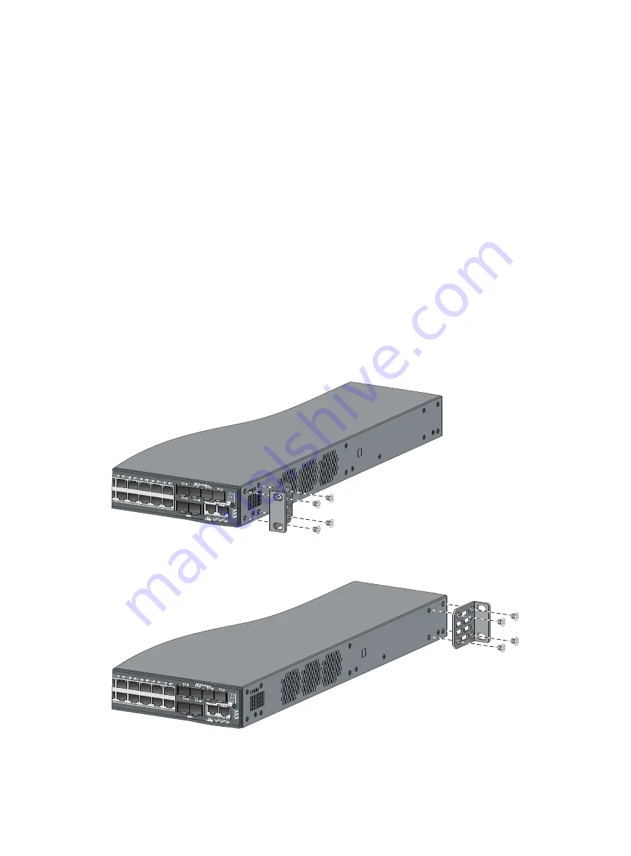
Attach the front mounting brackets to the chassis: 

a.


Unpack the front mounting brackets and the M4 screws (supplied with the switch) for attaching 
the brackets to the switch chassis. 

b.


Align the round holes in the wide flange of one front mounting bracket with the screw holes in 
the port-side mounting position (see 

Figure 16

) or power-side mounting position (see 

Figure 

17

).  

c.


Use M4 screws to attach the mounting bracket to the chassis.  

d.


Repeat the proceeding two steps to attach the other mounting bracket to the chassis. 

Figure 16


Attaching the front mounting bracket to the port side 


Figure 17


Attaching the front mounting bracket to the power side 


4.


Mount the chassis to the rack: 

Summary of Contents for 5500 HI Series

Page 1: ...HP 5500 HI Switch Series Installation Guide Part number 5998 2373 Document version 6W102 20130601 ...

Page 2: ...IS MATERIAL INCLUDING BUT NOT LIMITED TO THE IMPLIED WARRANTIES OF MERCHANTABILITY AND FITNESS FOR A PARTICULAR PURPOSE Hewlett Packard shall not be liable for errors contained herein or for incidental or consequential damages in connection with the furnishing performance or use of this material The only warranties for HP products and services are set forth in the express warranty statements accom...

Page 3: ...nding the switch with a grounding strip 17 Grounding the switch with a grounding conductor buried in the earth ground 19 Grounding the switch by using the AC power cord 19 Installing removing a power supply 20 Installing a PSR150 series power supply 20 Removing a PSR150 series power supply 22 Installing a PSR720 56A PSR1110 56A power supply 22 Removing a PSR720 56A PSR1110 56A power supply 23 Conn...

Page 4: ...ot swappable power supplies 51 Interface cards 51 SFP SFP XFP transceiver modules and SFP CX4 cables 52 100 Mbps SFP transceiver modules 52 1000 Mbps SFP transceiver modules 53 10 Gbps SFP transceiver modules SFP cables 54 10 Gbps XFP transceiver modules 55 CX4 cables 56 Appendix C Ports and LEDs 57 Fixed ports 57 Console port 57 Management Ethernet port 57 10 100 1000Base T Ethernet port 57 100 1...

Page 5: ...iii Index 67 ...

Page 6: ...00 24G PoE 4SFP HI TAA 2 slots JG542A HP 5500 48G PoE 4SFP HI Switch with 2 Interface Slots BJNGA AD0020 5500 48G PoE 4SFP HI 2 slots JG680A HP 5500 48G PoE 4SFP HI TAA compliant Switch with 2 Interface Slots BJNGA AD0020 5500 48G PoE 4SFP HI TAA 2 slots JG543A HP 5500 24G SFP HI Switch with 2 Interface Slots BJNGA AD0021 5500 24G SFP HI 2 slots JG681A HP 5500 24G SFP HI TAA compliant Switch with ...

Page 7: ...ort LED mode switching button 14 Console port 15 Management Ethernet port Management 16 SFP port 17 100 1000Base X SFP port Figure 2 5500 24G 4SFP HI 2 slots rear panel 1 Grounding screw 2 Power supply slot 1 PWR1 3 Power supply slot 2 PWR2 4 Interface card slot 1 SLOT1 5 Interface card slot 2 SLOT2 NOTE The 5500 24G 4SFP HI 2 slots switch comes with two expansion interface card slots covered by f...

Page 8: ...S 13 Interface card 2 status LED SLOT2 14 Interface card 1 status LED SLOT1 15 Management Ethernet port LED ACT LINK 16 SFP port 17 SFP port LED Figure 4 5500 48G 4SFP HI 2 slots rear panel 1 Grounding screw 2 Power supply slot 1 PWR1 3 Power supply slot 2 PWR2 4 Interface card slot 1 SLOT1 5 Interface card slot 2 SLOT2 NOTE The 5500 48G 4SFP HI 2 slots switch comes with two expansion interface ca...

Page 9: ...utton 14 Console port 15 Management Ethernet port Management 16 SFP port 17 10 100 1000 Base T auto sensing Ethernet port Figure 6 5500 24G SFP HI 2 slots 5500 24G SFP HI TAA 2 slots rear panel 1 Grounding screw 2 Power supply slot 1 PWR1 3 Power supply slot 2 PWR2 4 Interface card slot 1 SLOT1 5 Interface card slot 2 SLOT2 NOTE The 5500 24G SFP HI 2 slots switch and 5500 24G SFP HI TAA 2 slots sw...

Page 10: ...nterface card 2 status LED SLOT2 13 Port LED mode switching button 14 Console port 15 Management Ethernet port Management 16 SFP port 17 100 1000 Base X SFP port Figure 8 5500 24G PoE 4SFP HI 2 slots 5500 24G PoE 4SFP HI TAA 2 slots rear panel 1 Grounding screw 2 Interface card slot 1 SLOT1 3 Interface card slot 2 SLOT2 4 Power supply slot 1 PWR1 5 Power supply slot 2 PWR2 NOTE The 5500 24G PoE 4S...

Page 11: ...tatus LED PWR2 12 System status LED SYS 13 Interface card 2 status LED SLOT2 14 Interface card 1 status LED SLOT1 15 Management Ethernet port LED ACT LINK 16 SFP port 17 SFP port LED Figure 10 5500 48G PoE 4SFP HI 2 slots 5500 48G PoE 4SFP HI TAA 2 slots rear panel 1 Grounding screw 2 Interface card slot 1 SLOT1 3 Interface card slot 2 SLOT2 4 Power supply slot 1 PWR1 5 Power supply slot 2 PWR2 NO...

Page 12: ...cing FRUs including interface cards and power supplies wear an ESD preventive wrist strap to avoid damaging the units Examining the installation site The 5500 HI switches must be used indoors You can mount your switch in a rack or on a workbench but make sure Adequate clearance is reserved at the air inlet and exhaust vents for ventilation The rack or workbench has a good ventilation system Identi...

Page 13: ...ids and sulfides to eliminate corrosion and premature aging of components as shown in Table 3 Table 3 Harmful gas limits in the equipment room Gas Maximum concentration mg m3 SO2 0 2 H2S 0 006 NH3 0 05 Cl2 0 01 EMI All electromagnetic interference EMI sources from outside or inside of the switch and application system adversely affect the switch in a conduction pattern of capacitance coupling indu...

Page 14: ...9 WARNING Do not stare into any fiber port when the switch has power The laser light emitted from the optical fiber may hurt your eyes ...

Page 15: ...iable for any consequence Figure 11 Hardware installation flow Connect the grounding cable Mount the switch Start Connect power cords Verify the installation Power on the switch Install power supplies Operating properly Power off the switch Troubleshoot No Yes Install an interface card Install the interface card Yes Troubleshoot Yes No End No Operating properly Install pluggable modules or cables ...

Page 16: ...ack mounting restrictions and guidelines Mounting method Restrictions and guidelines Rack mounting by using front mounting brackets Only applicable to the 5500 24G 4SFP HI 2 slots 5500 48G 4SFP HI 2 slots 5500 24G SFP HI 2 slots and 5500 24G SFP HI TAA 2 slots switches Install the front mounting brackets at the port side or power side mounting position as needed For the 5500 48G 4SFP HI 2 slots if...

Page 17: ...slots One pair of 1U front mounting brackets See Figure 14 Supplied with the switch Supplied with the switch One pair of 1U rear mounting brackets two load bearing screws See Figure 15 Not supported Supplied with the switch Figure 14 Front mounting bracket 1 Hole for attaching to a rack 2 Hole for attaching to the switch chassis Figure 15 Rear mounting bracket and load bearing screw 1 Hole for att...

Page 18: ...he front mounting brackets to the chassis a Unpack the front mounting brackets and the M4 screws supplied with the switch for attaching the brackets to the switch chassis b Align the round holes in the wide flange of one front mounting bracket with the screw holes in the port side mounting position see Figure 16 or power side mounting position see Figure 17 c Use M4 screws to attach the mounting b...

Page 19: ...by using front and rear mounting brackets This mounting method is applicable to only the 5500 24G PoE 4SFP HI 2 slots 5500 24G PoE 4SFP HI TAA 2 slots 5500 48G PoE 4SFP HI 2 slots and 5500 48G PoE 4SFP HI TAA 2 slots switches You can install the front mounting brackets at the port side or power side mounting position as needed The following takes port side mounting as an example The power side mou...

Page 20: ...eps to attach the other mounting bracket to the chassis 3 Attach the load bearing screws to the chassis and the rear mounting brackets to the rack a Unpack the rear mounting brackets and the load bearing screws b Install the load bearing screws in one of the load bearing screw mounting positions see Figure 20 as needed Figure 20 Attaching the front mounting brackets and load bearing screws to the ...

Page 21: ...th M6 screws user supplied to the front rack posts Make sure the front and rear mounting brackets have securely attached the switch to the rack Figure 22 Mounting the switch in the rack Mounting the switch on a workbench IMPORTANT Ensure good ventilation and 10 cm 3 9 in of clearance around the chassis for heat dissipation Avoid placing heavy objects on the switch To mount the switch on a workbenc...

Page 22: ...itch with a grounding conductor buried in the earth ground Grounding the switch by using the AC power cord NOTE The power and grounding terminals in this section are for illustration only Grounding the switch with a grounding strip WARNING Connect the grounding cable to the grounding system in the equipment room Do not connect it to a fire main or lightning rod If a grounding strip is available at...

Page 23: ...per and insert the bare metal part through the black insulation covering into the end of the ring terminal supplied with the switch 8 Secure the metal part of the cable to the ring terminal with a crimper cover the joint with the insulation covering and heat the insulation covering with a blow dryer to completely cover the metal part 9 Connect the ring terminal to the grounding post of the groundi...

Page 24: ...tection Figure 26 Grounding the switch by burying the grounding conductor into the earth ground 1 Grounding screw 2 Chassis rear panel 3 Grounding cable 4 Earth 5 Joint 6 Grounding conductor Grounding the switch by using the AC power cord If the installation site has no grounding strips or earth ground you ground an AC powered switch through the PE wire of the power cord Make sure that The power c...

Page 25: ...ncy mode you can replace a power supply without powering off the switch but must strictly follow the installation and procedures in Figure 28 and Figure 29 to avoid any bodily injury or damage to the switch Figure 28 Installation procedure Figure 29 Removal procedure Installing a PSR150 series power supply CAUTION To prevent damage to the power supply or the connectors on the backplane insert the ...

Page 26: ...support its bottom with the other and slide the power supply slowly along the guide rails into the slot see callout 1 in Figure 30 4 Fasten the captive screws on the power supply with a Phillips screwdriver to secure the power supply in the chassis see callout 2 in Figure 30 If the captive screw cannot be tightly fastened check the installation of the power supply 5 Install the filler panel over t...

Page 27: ...Install the filler panel to prevent dust and ensure proper ventilation if no power supply is installed in the slot Installing a PSR720 56A PSR1110 56A power supply CAUTION To prevent damage to the power supply or the connectors on the backplane insert the power supply gently If you encounter a hard resistance while inserting the power supply pull out the power supply and insert it again For the PS...

Page 28: ...adds 64 mm 2 52 in to the depth of the switch as shown in Figure 33 4 Install the filler module over the empty power supply slot to prevent dust and ensure proper ventilation if you install only one power supply Figure 32 Installing the power supply Figure 33 PSR1110 56A in the chassis Removing a PSR720 56A PSR1110 56A power supply To remove a power supply 1 Wear an ESD preventive wrist strap and ...

Page 29: ...ch provides one filler module for the power supply slot To prevent dust and ensure good ventilation promptly install a filler module for an empty power supply slot To do so slide the filler module slowly along the guide rails into the slot until you hear that the latch of the filler module clicks into the slot as shown in Figure 35 IMPORTANT When you install a filler module make sure the blade of ...

Page 30: ...thead screwdriver through the handle and pull the filler module outward along the guide rails as shown in Figure 36 Put away the removed filler module for future use Figure 36 Removing a filler module Connecting the power cord Table 5 Power cord connection procedures at a glance Power supply Connection procedure reference PSR150 A JD362A PSR150 A1 JD362A Connecting the PSR150 A PSR150 A1 ...

Page 31: ...act and is well grounded 2 Connect one end of the AC power cord supplied with the power supply to the power receptacle on the power supply see Figure 37 3 Connect the other end of the AC power cord to an AC power outlet Figure 37 Connecting the PSR150 A Connecting the PSR150 D PSR150 D1 WARNING Identify the positive and negative marks on the two wires to avoid connection mistakes The following tak...

Page 32: ...ut you must purchase the power cord separately Figure 38 Connecting the PSR150 D Connecting the PSR720 56A PSR1110 56A The following takes the PSR720 56A as an example The connection procedure for the PSR1 1 10 56A is similar To connect the PSR720 56A 1 Wear an ESD preventive wrist strap and make sure it makes good skin contact and is well grounded 2 Plug the female connector end of the AC power c...

Page 33: ... 5500 24G 4SFP HI 2 slots 5500 24G SFP HI 2 slots 5500 24G SFP HI TAA 2 slots 5500 24G PoE 4SFP HI 2 slots and 5500 24G PoE 4SFP HI TAA 2 slots switches you can install the LSP5GP8P0 JG314A and LSP5GT8P JG313A cards only in SLOT1 To install an interface card 1 Wear an ESD preventive wrist strap and make sure it makes good skin contact and is well grounded 2 Loosen the mounting screws on the filler...

Page 34: ...push the interface card in along the slot guide rails until the interface card is in close contact with the switch chassis see callout 1 in Figure 41 4 Tighten the captive screws with a Phillips screwdriver to secure the interface card in the slot see callout 2 in Figure 41 Figure 41 Installing an interface card Figure 42 LSP5GT8P in the chassis ...

Page 35: ...akes good skin contact and is well grounded 2 Use a Phillips screwdriver to completely loosen the captive screws at both sides of the interface card 3 Gently pull the interface card along the guide rails until it completely comes out of the switch chassis Installing removing a CX4 SFP cable This section assumes that you have installed a CX4 SFP interface card The installation and removal procedure...

Page 36: ...nd make sure it makes good skin contact and is well grounded 2 Hold the cable connector and pull the pull latch of the connector to remove the cable from the switch Verifying the installation After you complete the installation verify that There is enough space for heat dissipation around the switch and the rack or workbench is stable The grounding cable is securely connected The correct power sou...

Page 37: ...the console cable Console cable A console cable is an 8 core shielded cable with a crimped RJ 45 connector at one end for connecting to the console port of the switch and a DB 9 female connector at the other end for connecting to the serial port on the console terminal Figure 45 Console cable Connection procedure To connect a terminal for example a PC to the switch 1 Plug the DB 9 female connector...

Page 38: ...meters To configure and manage the switch you must run a terminal emulator program on the console terminal The following are the required terminal settings Bits per second 9 600 Data bits 8 Parity None Stop bits 1 Flow control None Emulation VT100 To set terminal parameters for example on a Windows XP HyperTerminal 1 Select Start All Programs Accessories Communications HyperTerminal The Connection...

Page 39: ... by the HyperTerminal connection 4 Set Bits per second to 9600 Data bits to 8 Parity to None Stop bits to 1 and Flow control to None and click OK Figure 48 Setting the serial port parameters 5 Select File Properties in the HyperTerminal window ...

Page 40: ...35 Figure 49 HyperTerminal window 6 On the Settings tab set the emulation to VT100 and click OK Figure 50 Setting terminal emulation in Switch Properties dialog box ...

Page 41: ...ring the startup process you can access Boot ROM menus to perform tasks such as software upgrade and file management The Boot ROM interface and menu options differ with software versions For more information about Boot ROM menu options see the software matching release notes for the device After the startup completes you can access the CLI to configure the switch NOTE For more information about th...

Page 42: ...tches into a virtual switch called an IRF fabric or IRF virtual device for flattened network topology and high availability scalability and manageability IMPORTANT To set up IRF connection between 5500 HI switches you must use 10 Gigabit ports IRF fabric setup flowchart Figure 51 IRF fabric setup flowchart To set up an IRF fabric ...

Page 43: ...t distance Use XFP transceiver modules and fibers to connect XFP ports over a long distance Use SFP transceiver modules and fibers to connect SFP ports over a long distance or use SFP cables to connect SFP ports over a short distance All switches except the master switch automatically reboot and the IRF fabric is established Planning IRF fabric setup This section describes issues that an IRF fabri...

Page 44: ...ges to a daisy chain topology without interrupting network services You connect the IRF member switches through IRF ports the logical interfaces for the connections between IRF member switches Each IRF member switch has two IRF ports IRF port 1 and IRF port 2 To use an IRF port you must bind at least one physical port to it When connecting two neighboring IRF member switches you must connect the p...

Page 45: ...he front panel Ports on the 10GE XFP SFP CX4 interface cards on the rear panel The two SFP ports on the front panel and 10 Gigabit ports on the expansion interface card can be bound to any IRF port 5500 48G 4SFP HI 2 slots 5500 48G PoE 4SFP HI 2 slots 5500 48G PoE 4SFP HI TAA 2 slots The two fixed SFP ports on the front panel Ports on the 10GE XFP SFP CX4 interface cards on the rear panel Physical...

Page 46: ... Gbps XFP transceiver modules and CX4 cables The following subsections describe several HP recommended IRF connection schemes and all these schemes use a ring topology IMPORTANT In these schemes all physical IRF ports are located on the same side If physical IRF ports are on different sides you must measure the distance between them to select an appropriate cable Connecting the IRF member switches...

Page 47: ...42 Figure 54 Connecting the switches in the same rack Figure 55 IRF fabric topology ...

Page 48: ...IRF port you must install the interface card first For how to install an interface card see Installing removing an interface card Execute the display irf configuration command to verify the basic IRF settings For more information about configuring basic IRF settings see HP 5500 HI Switch Series IRF Configuration Guide Connecting the physical IRF ports Use CX4 SFP cables or XFP SFP transceiver modu...

Page 49: ...on and running status To do Use the command Display information about the IRF fabric display irf Display all members configurations that take effect after switch reboots display irf configuration Display topology information about the IRF fabric display irf topology NOTE To avoid IP address collision and network problems configure at least one multi active detection MAD mechanism to detect the pre...

Page 50: ...the system status LED and the seven segment LED of a 5500 HI switch to identify a fan failure If both LEDs are behaving as described in Table 8 a fan failure occurs Table 8 LED behaviors that identify a fan failure LED Mark State System status LED SYS Steady red Seven segment LED Unit The LED displays a flashing F character The 5500 HI Switch Series uses fixed fans If a fan failure occurs promptly...

Page 51: ...em and the terminal settings are correct Garbled terminal display If terminal display is garbled verify that the following settings are configured for the terminal for example HyperTerminal Baud rate 9 600 Data bits 8 Parity none Stop bits 1 Flow control none Emulation VT100 ...

Page 52: ...ernet ports 4 100 1000Base X SFP ports 2 x 1 10 Gbps SFP ports 24 100 1000Base X SFP ports 4 10 100 1000Base T auto sensing Ethernet ports 2 1 10 Gbps SFP ports Expansion interface card slots 2 SLOT1 and SLOT2 on the rear panel 2 SLOT1 and SLOT2 on the rear panel 2 SLOT1 and SLOT2 on the rear panel Power supply slots 2 on the rear panel 2 on the rear panel 2 on the rear panel Input voltage AC inpu...

Page 53: ... 1000Base T auto sensing Ethernet ports 4 100 1000Base X SFP ports 2 1 10 Gbps SFP ports 48 10 100 1000Base T auto sensing Ethernet ports 4 100 1000Base X SFP ports 2 x 1 10 Gbps SFP ports Expansion interface card slots 2 SLOT1 and SLOT2 on the rear panel 2 SLOT1 and SLOT2 on the rear panel Power supply slots 2 on the rear panel 2 on the rear panel Input voltage PSR720 56A JG544A AC input Rated vo...

Page 54: ...ed fans and left right aisles for air ventilation Ambient air flows in through the air vents at the left side of chassis the direction subject to the user facing the front panel of the chassis circulates through the chassis and the power supplies and exhausts at the right side of the chassis and the air outlet vents of the power supplies The chassis and power supplies use independent aisles which ...

Page 55: ...d Supported N A N A PSR150 A1 JD362A Supported Supported Supported N A N A PSR150 D1 JD366A Supported Supported Supported N A N A PSR720 56A JG544A N A N A N A Supported Supported PSR1110 56A JG545A N A N A N A Supported Supported Interface cards LSPM1XP1P JD361B Supported Supported Supported Supported Supported LSPM1XP2P JD359B Supported Supported Supported Supported Supported LSPM1CX2P JD360B Su...

Page 56: ...ave different PoE power For more information see Table 10 Hot swappable power supplies Product code Power supply Specifications Reference JD362A PSR150 A PSR150 A1 Rated input voltage range 100 VAC to 240 VAC 50 Hz or 60 Hz Max input voltage range 90 VAC to 264 VAC 47 Hz to 63 Hz Max output power 150 W HP PSR150 A PSR150 D Series Power Supplies User Guide JD366A PSR150 D PSR150 D1 Rated input volt...

Page 57: ...f the switch For more information about the interface cards see their user guides SFP SFP XFP transceiver modules and SFP CX4 cables This section describes the transceiver modules and transceiver module cables available for the HP 5500 HI Switch Series IMPORTANT The operating temperature is 0 C to 45 C 32 F to 113 F for the JD121A and JD107A transceiver modules and 0 C to 50 C 32 F to 122 F for al...

Page 58: ...sceiver TX 1550 RX 1310 9 125 15 km 9 32 miles IMPORTANT You must use the transceiver modules coded D100A and JD101A in pairs 1000 Mbps SFP transceiver modules Product code Module description Central wavelength nm Cable fiber diameter μm Multimode fiber modal bandwidth MHz km Max transmission distance JD118B HP X120 1G SFP LC SX Transceiver 850 50 125 500 550 m 1804 46 ft 400 500 m 1640 42 ft 62 5...

Page 59: ...ir N A 100 m 328 08 ft IMPORTANT You must use the transceiver modules coded JD098B and JD099B in pairs 10 Gbps SFP transceiver modules SFP cables Product code Module description Central wavelength nm Fiber diameter μm Multimode fiber modal bandwidth MHz km Max transmission distance Transceiver modules JD092B HP X130 10G SFP LC SR Transceiver 850 50 125 2000 300 m 984 25 ft 500 82 m 269 03 ft 400 6...

Page 60: ... N A 5 m 16 40 ft JC784C HP X240 10G SFP SFP 7m Direct Attach Copper Cable N A SFP cable N A 7 m 22 97 ft Figure 57 SFP cable 1 Pull latch 2 Connector 10 Gbps XFP transceiver modules Product code Module description Central wavelength nm Fiber diameter μm Multimode fiber modal bandwidth MHz km Max transmission distance JD117B HP X130 10G XFP LC SR Transceiver 850 50 125 2000 300 m 984 25 ft 500 82 ...

Page 61: ...Transceiver 1550 9 125 N A 80 km 49 71 miles CX4 cables Product code CX4 cable model Connector Max transmission distance JD363B HP X230 Local Connect 50cm CX4 Cable 4X Infiniband 0 5 m 1 64 ft JD364B HP X230 Local Connect 100cm CX4 Cable 4X Infiniband 1 m 3 28 ft JD365A HP X230 CX4 to CX4 3m Cable 4X Infiniband 3 m 9 84 ft Figure 58 CX4 cable assembly 1 Pull latch 2 Connector ...

Page 62: ...port You can connect this port to a PC or management station for loading and debugging system software or remote management Table 12 Management Ethernet port specifications Item Specification Connector type RJ 45 Port transmission rate 10 100 Mbps half full duplex auto MDI MDI X 1000 Mbps full duplex auto MDI MDI X Transmission medium Category 5 or above twisted pair cable Max transmission distanc...

Page 63: ...transceiver modules SFP cables into the SFP ports as needed You can use the SFP ports as IRF physical ports to connect 5500 HI switches in an IRF deployment LEDs System status LED The system status LED shows the operating status of the switch Table 14 System status LED description LED mark Status Description SYS Steady green The switch is operating properly Flashing green 1 Hz The switch is perfor...

Page 64: ...E 4SFP HI TAA 2 slots The network port LEDs are showing the status of PoE power supply on the ports Steady yellow The network port LEDs are showing duplex modes Seven segment LED The seven segment LED together with the system status LED shows detailed system operating information see Table 17 Table 17 Seven segment LED description I System status LED SYS status Seven segment LED Unit status Descri...

Page 65: ...status Description Port mode LED Mode System status LED SYS Seven segment LED Unit Flashing green 1 Hz PoE mode Steady green The LED displays different signs For example the sign indicates that the switch is outputting 0 to 20 of the maximum PoE output power Management Ethernet port LED The management Ethernet port has a port LED to show its operating status and activities The port mode LED indica...

Page 66: ... mode Steady green The port is operating at 1000 Mbps The port LED fast flashes when the port is sending or receiving data Steady yellow The port is operating at 10 100 Mbps The port LED fast flashes when the port is sending or receiving data Flashing yellow 3 Hz POST has failed on the port Off No link is present on the port Flashing green 1 Hz PoE mode supported by 5500 24G PoE 4SFP HI 2 slots 55...

Page 67: ... has failed on the port Off No link is present on the port SFP port LED Each SFP port has a status LED to show port operating status and activities The port mode LED indicates the type of information for example port rate or duplex mode that the port LEDs are showing You can use the port LED mode switching button to change the type of displayed port information Table 22 SFP port LED description Po...

Page 68: ...ption for the LSPM2SP2P interface card Port mode LED Mode Port LEDs on the LSPM2SP2P card Description Steady green rate mode or flashing green 1 Hz PoE mode Steady green The port is operating at 10 Gbps The port LED fast flashes when the port is sending or receiving data Steady yellow The port is operating at 1 Gbps The port LED fast flashes when the port is sending or receiving data Flashing yell...

Page 69: ...ng you will receive email notification of product enhancements new driver versions firmware updates and other product resources Related information Documents To find related documents browse to the Manuals page of the HP Business Support Center website http www hp com support manuals For related documentation navigate to the Networking section and select a networking category For a complete list o...

Page 70: ...parated by vertical bars from which you select one choice multiple choices or none 1 n The argument or keyword and argument combination before the ampersand sign can be entered 1 to n times A line that starts with a pound sign is comments GUI conventions Convention Description Boldface Window names button names field names and menu items are in bold text For example the New User window appears cli...

Page 71: ... 2 features Represents an access controller a unified wired WLAN module or the switching engine on a unified wired WLAN switch Represents an access point Represents a security product such as a firewall a UTM or a load balancing or security card that is installed in a device Represents a security card such as a firewall card a load balancing card or a NetStream card Port numbering in examples The ...

Page 72: ...es 50 G Grounding the switch 17 H Hot swappable power supplies 51 I Installing the switch in a 19 inch rack 1 1 Installing removing a power supply 20 Installing removing an interface card 28 Interface cards 51 IRF fabric setup flowchart 37 L LEDs 58 M Mounting the switch on a workbench 16 P Planning IRF fabric setup 38 Power supply failure 45 Powering on the switch 36 R Related information 64 S Sa...

Reviews: