


279
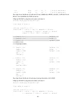
<RouterC> display ip routing-table 1.1.1.0 24 verbose
Summary Count : 1
Destination: 1.1.1.0/24
Protocol: BGP Process ID: 0
SubProtID: 0x1 Age: 00h03m08s
Cost: 100 Preference: 255
Tag: 0 State: Active Adv
OrigTblID: 0x1 OrigVrf: default-vrf
TableID: 0x2 OrigAs: 0
NBRID: 0x15000000 LastAs: 0
AttrID: 0x0 Neighbor: 2.0.1.1
Flags: 0x10060 OrigNextHop: 2.0.1.1
Label: NULL RealNextHop: 2.0.2.1
BkLabel: NULL BkNextHop: N/A
Tunnel ID: Invalid Interface: Ethernet1/2
BkTunnel ID: Invalid BkInterface: N/A
The output shows that Router C communicates with network 1.1.1.0/24 through the path Router
C<—>Router D<—>Router A.
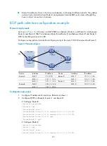
IPv6 BGP configuration examples
IPv6 BGP basic configuration example
Network requirements
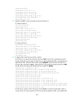
As shown in
, run EBGP between Router A and Router B, and run IBGP between Router B and
Router C so that Router C can access the network 50::/64 connected to Router A.
Figure 72
Network diagram
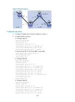
Configuration procedure
1.
Configure IP addresses for interfaces. (Details not shown.)
2.
Configure IBGP:
# Configure Router B.
<RouterB> system-view
[RouterB] bgp 65009
[RouterB-bgp] router-id 2.2.2.2
[RouterB-bgp] peer 9::2 as-number 65009