


379
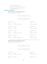
Destination : 2001:4::1 PrefixLen: 128
Flag : R/-/- Cost : 10
Next Hop : FE80::20F:E2FF:FE3E:FA3D Interface: Eth1/3
Flags: D-Direct, R-Added to Rib, L-Advertised in LSPs, U-Up/Down Bit Set
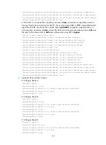
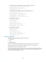
# Display the IPv6 IS-IS routing table on Router D.
[RouterD] display isis route ipv6
Route information for IS-IS(1)
------------------------------
Level-2 IPv6 Forwarding Table
-----------------------------
Destination : 2001:1:: PrefixLen: 64
Flag : R/-/- Cost : 20
Next Hop : FE80::200:FF:FE0F:4 Interface: Eth1/1
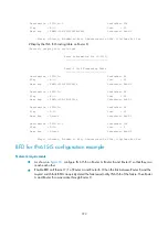
Destination : 2001:2:: PrefixLen: 64
Flag : R/-/- Cost : 20
Next Hop : FE80::200:FF:FE0F:4 Interface: Eth1/1
Destination : 2001:3:: PrefixLen: 64
Flag : D/L/- Cost : 10
Next Hop : Direct Interface: Eth1/1
Destination : 2001:4::1 PrefixLen: 128
Flag : D/L/- Cost : 0
Next Hop : Direct Interface: Eth1/2
Flags: D-Direct, R-Added to Rib, L-Advertised in LSPs, U-Up/Down Bit Set
BFD for IPv6 IS-IS configuration example
Network requirements
•
As shown in
, configure IPv6 IS-IS on Router A, Router B, and Router C so that they can
reach each other.
•
Enable BFD on Ethernet 1/1 of Router A and Router B. When the link between Router B and the
Layer-2 switch fails, BFD can quickly detect the failure and notify IPv6 IS-IS of the failure. Then Router
A and Router B communicate through Router C.