background image

16 


Connector repair


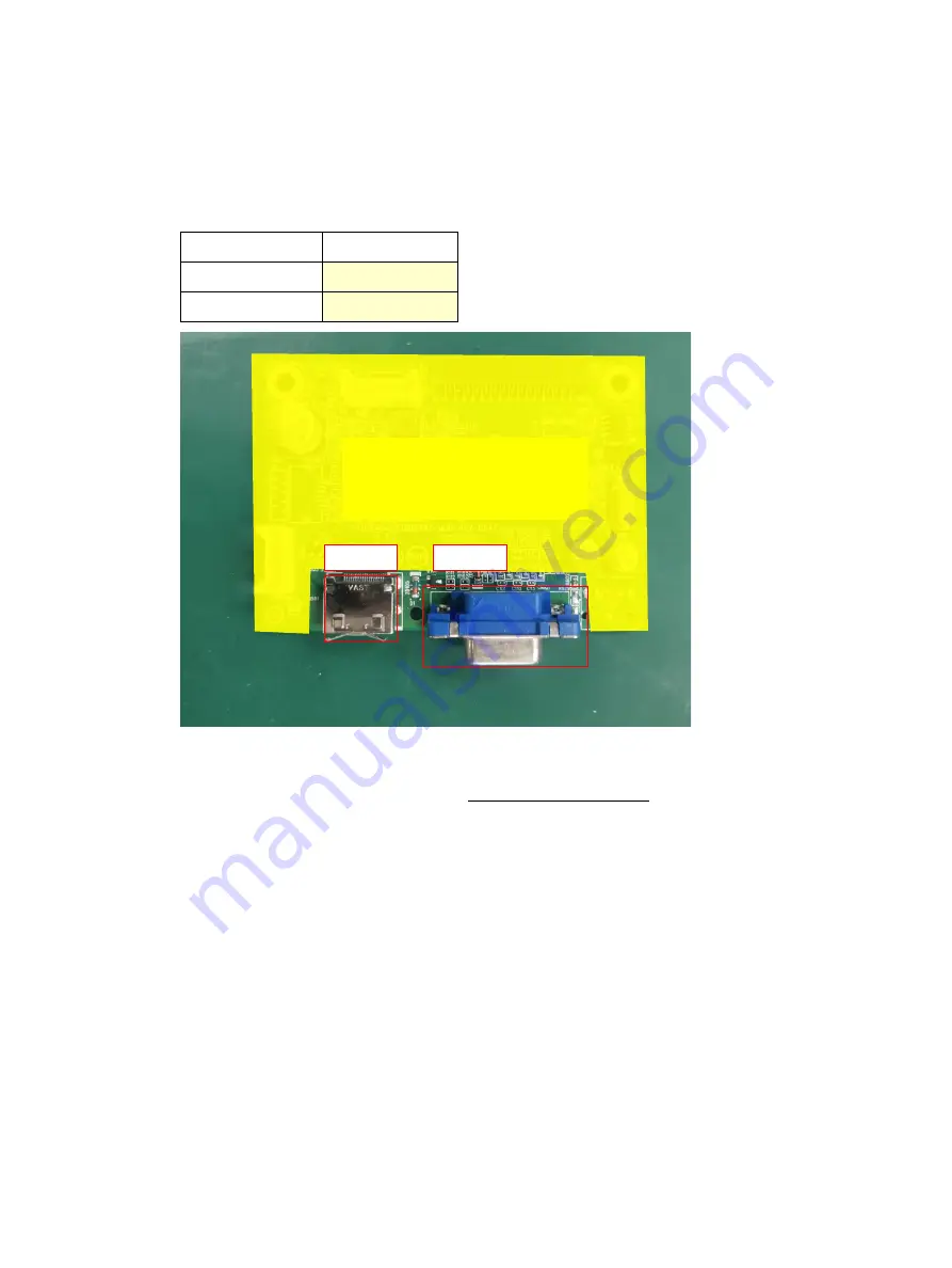
This procedure includes HDMI, D-sub connectors. 
The connectors are on the main board(spare part number CBPCLC3HPQ1). 
The connectors identifiers are as follows: 

Connector 

Location 

HDMI  

CN501 

D-sub  

CN101 


Before repairing connectors, follow these steps: 


Prepare the monitor for disassembly. See Preparation for disassembly on page 9. 

IMPORTANT: 


• 

Repair Condition: Connector repair is only for out of warranty. 


• 

Repairing must operate by professional repairers (Note) in repair center, not applicable for end user. 


• 

Electrostatic protection is required when component replacement is required. 


• 

The monitor meets ROHS, please use Lead-free solder wire for soldering. 


• 

If Connector need to replace, must check specification and part number whether match the BOM and 

location. 


• 

If connector need to replace, please insert new parts carefully because the near pin may cause short 

circuit by inappropriate operate. 


• 

DO NOT allow any liquid on the board. Water and moisture may cause short-circuit to the electronic 

components and lead to malfunctions. 


• 

The fusion point of Lead-Free solder is requested. Repairing with conventional lead wire may cause 

damage. 


• 

Work quickly to avoid overheating the circuit board as soon as you confirm the steady soldering 

condition. 


• 

Keep the soldering iron tip clean and well tinned and when replacing parts. 


• 

A close inspection of the circuit board revealed look in good condition. 


Main Board 

CN501 

CN101 

Summary of Contents for 2UD96AA

Page 1: ...Maintenance and Service Guide 32s model SUMMARY This guide provides information about spare parts removal and replacement of parts diagnostic tests problem troubleshooting and more ...

Page 2: ...d States and other countries The information contained herein is subject to change without notice The only warranties for HP products and services are set forth in the express warranty statements accompanying such products and services Nothing herein should be construed as constituting an additional warranty HP shall not be liable for technical or editorial errors or omissions contained herein Fir...

Page 3: ...ore returning the repaired product to the customer 2 2 Monitor features 3 Front components 4 Locating the serial number and product number 5 3 Illustrated parts catalog 7 How to order parts 8 4 Removal and replacement procedures 9 Preparation for disassembly 9 RC 10 Power board 15 Connector repair 16 HDMI connector CN501 17 D sub connector CN101 18 Function test 19 Support and troubleshooting 19 ...

Page 4: ......

Page 5: ...pening the product s cabinet Modules containing electrical components are sensitive to electrostatic discharge ESD Follow ESD safety procedures while handling these parts Some products contain more than one battery Do not disassemble or expose a battery to high temperatures such as throwing into fire or the battery may explode Refer to government requirements for battery recycling or disposal This...

Page 6: ...tance in Electrical and Electronic Equipment Directive is a legal requirement by the EU European Union for the global electronics industry sold in the EU and other countries Any electrical and electronics products launched in the market after June 2006 should meet this RoHS requirement Products launched in the market before June 2006 are not required to be compliant with RoHS parts If the original...

Page 7: ...ck slot for a locking security cable security cable sold separately Plug and Play capability if supported by your computer system On Screen Display OSD adjustments in several languages for easy setup and screen optimization Energy saver feature to meet requirements for reduced power consumption HDCP High bandwidth Digital Content Protection copy protection on all digital inputs NOTE For safety and...

Page 8: ...ivate the Menu button and the Function buttons press anyof the buttons so that the button labels appear on the screen 2 Function buttons Use these buttons to navigate through the OSD menu based on the indicators next to the buttons that are activated while the OSD menu isopen NOTE You can reconfigure the Function buttons in the OSD menu toquickly select the most commonly used operations 3 Power bu...

Page 9: ...ct number The rating label on the monitor provides the product number and serial number You may need these numbers when contacting HP about your monitor model The rating label is on the back of the monitor For worldwide models except India ...

Page 10: ...6 For India Bar code label Spec label ...

Page 11: ...6 MAINFRAME 7 MAINFRAME 8 KEY BOARD 9 LENS 10 KEY BOARD 11 KEY No Description 12 BKT_WEBCAM S1 SCREW M4 4 BKT HINGE PANEL 13 REAR_COVER S2 SCREW M4 6 BKT HINGE PANEL 14 stand ass y NA AUO S3 SCREW D3 6 MAIN BOARD POWER BOARD MAINFRAME 15 COVER_HINGE S3 SCREW D3 6 MAIN BOARD POWER BOARD MAINFRAME 16 BKT_VESA S4 SCREW M3 8 KEY BOARD REAR COVER 17 PLUG S5 SCREW M4 10 STAND ASSY REAR COVER ...

Page 12: ...C917 and C919 Digi Key 25YXG470MEFC10X12 5 EC 470uf 20 25V 10X16 RS 4000 hr ERS1EM C916 and C918 Digi Key 25ZL470MEFC10X16 Connectors by manufacturer Component description Location identifier Component distributor Distributer part number HDMI CN501 RS SD 47151 001 Molex D sub CN101 tme HDL15 SL B ADAM TECH NOTE Rear cover and chassis need to be modified to hold connector Connector may need modific...

Page 13: ...ce information and precautions sections in the Getting started chapter of this guide 2 Clean the room for disassembly 3 Identify the disassembly area 4 Check the position that the monitors are to be placed along with the number of monitors Prepare the area for material flow according to the disassembly layout 5 Be sure to have the following equipment and materials Press fixture Working table Screw...

Page 14: ...follow these steps Prepare the monitor for disassembly See Preparation for disassembly on page 9 Step Figure Description Preparation Lay the monitor on a flat soft and clean surface Remove the base Remove the screws to remove base ...

Page 15: ...11 Remove the COVER_HINGE and remove the screws to remove the Hinge Remove the COVER_HINGE and remove the screws to remove the Hinge Remove the tapes Remove the tapes Remove the screws Remove the screws ...

Page 16: ...12 Remove the pins Remove the pins Remove the screws Remove the screws Remove the Mylar Remove the Mylar ...

Page 17: ...13 Remove the main board and power board Remove the screws to remove the main board and power board Remove the connectors Remove the connect pins The mainframe The mainframe ...

Page 18: ...14 The panel The panel The key board Remove the screws to remove the key board The rear cover The rear cover ...

Page 19: ...e monitor for disassembly See Preparation for disassembly on page 9 Remove the power board 1 The HP 32s power board connector position is as follows 2 Locate the part number location on the board Power Board Warning After unplugging the power supply the capacitance is still charged do not touch and discharge the capacitor ...

Page 20: ...s ROHS please use Lead free solder wire for soldering If Connector need to replace must check specification and part number whether match the BOM and location If connector need to replace please insert new parts carefully because the near pin may cause short circuit by inappropriate operate DO NOT allow any liquid on the board Water and moisture may cause short circuit to the electronic components...

Page 21: ...ional repairer where such system exists in the Member States concerned shall be accepted as proof of compliance with this point 2 The professional repairer is covered by insurance covering liabilities resulting from its activity regardless of whether this is required by the Member State HDMI connector CN501 Repair the HDMI connector 1 Use a soldering iron and a desoldering pump to remove as much s...

Page 22: ...ector 1 Use a soldering iron and a desoldering pump to remove as much solder as possible from the pin 2 Lift the CN101 connector from the PCB 3 Place the new component on the PCB Be sure that it matches the PCB footprint 4 Solder the new component ...

Page 23: ...t Brightness toadjust the brightness scale as needed Check Video Cable is displayed on screen Monitor video cable is disconnected Connect the appropriate video signal cable between the computer and monitor Be surethat the computer power is off while you connect the video cable Input Signal Out of Range is displayed on screen Video resolution and or refresh rate are set higher than what the monitor...

Page 24: ...ess and hold the Menu button on the frontbezel for 10 seconds to disable the OSD Lockout function Power Button Lockout is displayed The monitor s Power Button Lockout function is enabled Press and hold the Power button for 10 seconds to disable the Power Button Lockoutfunction ...

Reviews: