


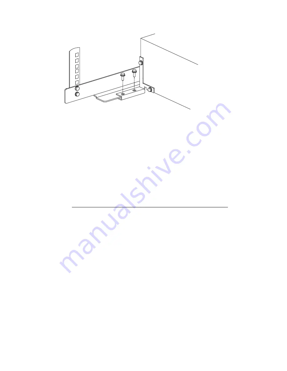
Figure 7: Securing the Chassis to the Rail
M6 x 12mm
Screw
Front Left
Rack Column
Rear of Interconnect
Chassis
1.
Using a #2 Phillips screwdriver and two M6 x 12-mm pan-head screws secure
the left retainer bracket to the rail through the threaded inserts in the bracket.
2.
Repeat step 1 for the right retainer bracket, using a total of four screws.
Tighten the screws to their specified torque.
11 Removing the Interconnect for Servicing
Bring the cluster to an appropriate state for switch component removal and put the
rack into a safe and stable state for component removal.
_______________________
WARNING
______________________
The HP 10642 rack is tall. To avoid potential injury, always use two
people and a stable, elevated work platform to remove components
from a high rack elevation.
1.
At the rack’s power distribution unit (PDU), power off the circuit that supplies
power to the interconnect. Disconnect the power cable at the rear of the
interconnect chassis.
2.
If necessary, mark the high-speed network cables to ensure that they can be
reconnected to their respective ports.
3.
Disconnect and remove each high-speed network cable bundle until all ports
are unplugged. Secure the cables out of the interconnect’s removal path.
4.
Depending on whether you are performing a complete disassembly or only
replacing a defective chassis, perform one of the following steps:
a.
Disassemble the installation
Use a #2 Phillips screwdriver to remove the four M6 x 12-mm Phillips
pan-head screws that secure each retainer bracket to the rail. The bracket
remains attached to the interconnect chassis (see Figure 7).
b.
Replace a chassis
Use a #1 Phillips screwdriver remove the four 6-32 x .375 in Phillips
pan-head screws that secure each retainer bracket to the chassis. The
bracket remains attached to the rail (see Figure 4).
5.
Remove the two M6 x 16-mm pan-head screws from each front bracket (see
Figure 5, callout 1).
6.
Slide the interconnect chassis all the way out of the rack.
Myrinet Interconnect Rack Kit Installation Guide 7


