Operating M anual
2-60-006-00-00563
Rev. A - 25/01/15
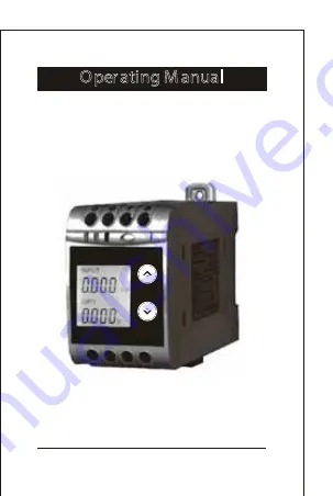
Programmable Frequency Transducer
Theta Hz
ON O/P1 O/P2
COM
a H
Thet
z
Page 1: ...Operating Manual 2 60 006 00 00563 Rev A 25 01 15 Programmable Frequency Transducer Theta Hz ON O P1 O P2 COM a H Thet z...
Page 2: ......
Page 3: ...ngareobserved All operations concerning installation electrical connection commissioning must be carried out by qualified skilled personal national regulations for the preventions of accidentsmustbeob...
Page 4: ...Setting 3 1 2 1 Address setting 3 1 2 2 RS 485 Baud Rate 3 1 2 3 RS 485 Parity Selection 3 1 3 Output Type selection 3 1 3 1 Output 1 Type selection 3 1 3 2 Output 2 Type selection 3 1 4 Input charact...
Page 5: ...cerusingoptional PRKAB601Adapter Installation 5 1 EMCInstallationRequirements 5 2 CaseDimensions 5 3 Wiring 5 4 AuxiliarySupply 5 5 Fusing 5 6 Earth GroundConnections 5 7 Maintenance 6 Specification 7...
Page 6: ...ut Frequency and Output Voltage Current are displayed onLCDandindicatedbyLED s Frequency Transducer can be configured and programmed at site for the following Input parameters i e start end and elbow...
Page 7: ...sing the Up key or by pressing Down key Screen 1 Display Test Screen 3 Frequency Input and Output 1 as Voltage Screen 4 Input and Output 1 as Current Frequency INPUT x012 O P 12 y012 A A ON O P1 O P2...
Page 8: ...imultaneouslyfor5seconds Thiswilltake theUserintothePasswordProtectionEntryStage 3 1 1 PasswordProtection 3 1 1 1PasswordVerification Password protection can be enabled to prevent unauthorisedaccessto...
Page 9: ...inthiscaseto 1 In the special case where the Password is 0000 pressing the v Up key when prompted for the first digit will advance tothe PasswordSet Confirmed screen EnterPassword firstdigit entered p...
Page 10: ...hevaluewill wrapfrom9 roundto0 Pressing the Up key will advance the operation to the Password Set Confirmed set thefourthdigit Inthiscaseto 4 PasswordSet Confirmed Pressing Down keywillenter tothe New...
Page 11: ...git entered prompting for second digit Denotes that digit will be flashing Pressing the Down key will scroll the value of the seconddigit from 0 through to 9 the valuewillwrapfrom9roundto0 Pressing th...
Page 12: ...sswordConfirmed andsetthefourthdigit inthiscaseto 1 New changedPasswordconfirmed Pressing the Down key will re enter to the New Password entry stage Pressing the Up key will confirm New Password and a...
Page 13: ...enext digit and set the second digit in thiscaseto 0 Enter New Change Address value second digit entered promptingforthirddigit Denotes that digit will be flashing Pressing the Down key will scroll th...
Page 14: ...irmNewAddressvalueand advancetotheBaudrate selection section3 1 2 2 3 1 2 2RS485BaudRate This screen allows the user to set BaudRateofRS485port The valuesdisplayed onscreenare inkbaud Pressingthe Down...
Page 15: ...enterthe Parity stopbitedit modeandscrollthevalue through odd oddparitywithonestopbit no 1S noparitywithonestopbit no 2S noparitywithtwostopbit E evenparitywithonestopbit Pressing Up key accepts the p...
Page 16: ...n section3 1 3 2 Output1confirmation Pressing Down key will re enter into Output 1 Type Edit mode Pressing Up key will confirm the present type for Output 1 and advance to Output 2 type selection sect...
Page 17: ...4 1 EndvalueofInput ThisscreenallowstheusertosettheEndvalueofInput EndvalueoftheInputcanbeselectedinbetween49to65Hz Pressing the Down key will enter the New Change End value of Input edit mode Pressi...
Page 18: ...the value of the second digit from 0 through to 9 the value will wrap from 9 round to 0 if first digit is 5 Pressing the Up key will advance the operation to the next digit and set the second digit i...
Page 19: ...seto 0 New changedEndvalueofInputconfirmed Pressing the Down key will re enter to the New Change EndvalueofInput Pressing the Up key will confirm New End value of Input and advance to the Start value...
Page 20: ...p key will advance the operation to the nextdigitandsetthefirstdigit inthiscaseto 4 Enter New Change Start value of Input first digit entered prompting for second digit Denotes that digit will be flas...
Page 21: ...wn key will scroll the value of the fourth digit from 0 through to 9 the value will wrap from 9 round to 0 depending on the set End value of Input Pressing the Up key will advance the operation to the...
Page 22: ...ion3 1 5 1 Elbow Function of Input confirmation Pressing Down key will re enterintoElbowfunctionof Input Edit mode Pressing the Up key will set the value and advance to the Elbow value of Input select...
Page 23: ...t digit and set the first digit inthiscaseto 5 Enter New Change Elbow value of the Input first digit entered prompting for second digit Denotes that digit will beflashing Pressing the Down key will sc...
Page 24: ...e Down key will scroll the value of the fourth digit from 0 through to 9 the value will wrapfrom9roundto0dependingonthesetEndvalueofInput Pressing the Up key will advance the operation to the New Chan...
Page 25: ...put 1 and advance to the Start value of Output1 setting section3 1 5 1 2 3 1 5 1 2 Startvalueofoutput1 This screen allows the user to set the Start value of Output 1 considered as DC Current Start val...
Page 26: ...y will scroll the value of the second digit from 0 through to 4 the value will wrap from 4roundto0dependingonthesetEndvalueofOutput Pressing the Up key will advance the operation to the nextdigitandse...
Page 27: ...ance the operation to the New Changed Start value of the Output 1 and set the fourthdigit inthiscaseto 0 New changed Start value of the Output 1 confirmed Pressing the Down key will re enter to the Ne...
Page 28: ...owvalueoftheOutput1 Denotesthatdigitwillbe flashing Pressing the Down key will scroll the value of the first digit from 0 through to 1 the value will wrapfrom1roundto0depending onthesetEndvalueofOutpu...
Page 29: ...p key will advance the operation to the next digit and set the third digit in this case to 0 Enter New Change Elbow value of the Output 1 third digit entered prompting for fourth digit denotes that di...
Page 30: ...value of Output 2 considered as DC Voltage for dual output The End value of VoltageOutputfixedat10V Pressing the Down key value remains constant because end valueisfixed Pressing Up key will set the...
Page 31: ...next digitandsetthefirstdigit inevery caseto 0 Enter New Change Start value of the Output 2 first digit entered prompting for second digit Denotes that digit will be flashing Pressing the Down key wil...
Page 32: ...wrapfrom9roundto0 Pressing the Up key will advance the operation to the New Changed Elbow value of the Output 2 confirmation andsetthefourthdigit inthiscaseto 0 New changedStartvalueof theOutput2confi...
Page 33: ...lueasElbowvalue of the Output 2 and exit setup menu New ChangeElbowvalueoftheOutput2 Denotes that digit will be flashing Pressing the Down key will scroll the value of the first digit from 0 through t...
Page 34: ...wrap from 9 round to 0 dependingthesetEndvalueofOutput Pressing the Up key will advance the operation to the nextdigitandsetthethirddigit inthiscaseto 0 Enter New Change Elbow value of the Output 2 t...
Page 35: ...AB601 Adapter A PC with RS 232 C interface along with the programming cable PRKAB601 and the configuration software are requiredtoprogramthetransducer Details of the programming cable and the software...
Page 36: ...gh MODBUS 3 3 1 DIP Switch Setting for Changing Output type The Transducer output type can be changed from DC current to DC voltage depending upon user requirement on site To change output type user h...
Page 37: ...DIP switch setting is done first and then output type parameter is configured using either of the above three methods then switch OFF ON the Transducer For changing DIP switches follow these steps 1...
Page 38: ...of arrow 6 After inserting the front cover insert the Interface card PCB and back cover Insert the Interface card PCB and Back cover press in direction of arrow 38 Switches of Output 2 can be set for...
Page 39: ...ype and length of cable used The impedance of the termination load should match the impedance of the cable and be at both ends of the line The cable should be terminated at each end with a 120 ohm 1 4...
Page 40: ...reviousquery and canissuefreshquerytotheslave TheeachbyteinRTUmode has followingformat 8 bit binary hexadecimal 0 9 A F 2 hexadecimal characters contained in each 8 bit field of the message 4 bytes 32...
Page 41: ...or reading measured values Two consecutive 16 bit registers represent one parameter Refer table 2 for the addresses of 3X registers Parameters measuredbytheinstruments Each parameter is held in the 3X...
Page 42: ...0Hz Device Address Function Code Byte Count Data Register1 High Byte Data Register1 Low Byte Data Register2 High Byte Data Register2 Low Byte CRC Low 01 Hex 04 Hex 04 Hex 42 Hex 48 Hex 00 Hex 00 Hex...
Page 43: ...ss Function Code Start Address High Start Address Low Number of Registers Hi Number of Registers Lo CRC Low CRC High 01 Hex 03 Hex 00 Hex 0E Hex 00 Hex 02 Hex A5 Hex C8 Hex Start Most significant 8 bi...
Page 44: ...ter Leastsignificant8bitsofDataregister 2LowByte 2oftheparameter requested Note Two consecutive 16 bit register represent one parameter Example Writing Device address Device address Start address 0E H...
Page 45: ...nt Totalnumberofdatabytesreceived Dataregister Most significant8bitsofDataregister 1HighByte 1oftheparameterrequested Dataregister Leastsignificant8bitsofDataregister 1LowByte 1oftheparameter requeste...
Page 46: ...umber of registerLo registers requested Note Twoconsecutive16bitregisterrepresentoneparameter Response 00 Hex 02 Hex 20 Hex 0B Hex Number of Registers Hi Number of Registers Lo CRC Low CRC High Table...
Page 47: ...ster This is used to select the Mode of operation Normalmode 1 Simulationmode 2 40003 Mode Selection This address is used to set the Device Address between 1 to 247 This address is used to set the Bau...
Page 48: ...s is used to set the simulation OutputBto10 ofOutput bywriting1000 and100 ofOutputbywriting10000 This address is used to set theAnalog O P Type1asVoltage Current Voltage 1 Current 2 This address is us...
Page 49: ...rdirectlyontoawalloramountingplate 2400 2400 EVEN ODD Baud Rate Parity Stop Bit Decimal value 01 01 02 03 The front of the enclosure conforms to IP 40 The terminals oftheproductshouldbe protectedfroml...
Page 50: ...e forEMCinindustrialenvironments e g 1 Screened output and low signal input leads or have provision for fitting RF suppression components such as ferrite absorbers line filters etc in the event that R...
Page 51: ...eet local regulations Terminal for both Current and Voltage inputswillacceptupto2x2 5mm or1x4mm cables 5 4 AuxiliarySupply it may be powered from the signal source provided the source remains within t...
Page 52: ...NominalinputVoltage U 57V U 500V N N NominalinputVoltageburden 0 6VAmax OverloadCapacity 1 continuously N for N minute MeasuringOutputY SingleorOptionalDual Output type Load independent DC Voltage or...
Page 53: ...Voltage output Voltage limit under R 1 25 Y2 with voltage output 30 V with current output Residual Ripple in 1 pk pk Output signal Response Time 300 ms Acc toIEC60688 Reference Value Output end Value...
Page 54: ...1 Example of setting with Linear characteristics 2 Example of setting with Bent characteristics X0 Start value of input Y0 Start value of output X1 Elbow value of input Y1 Elbow value of output X2 En...
Page 55: ...therversusoutersurface InstallationData MechanicalHousing Lexan940 polycarbonate Flammability Class V 0 acc To UL 94 self extinguishing non dripping freeofhalogen Mountingposition Railmounting wallmou...
Page 56: ...IEC61326 Electromagnetic compatibility Reference conditions for Accuracy Ambient temperature 23 C 1 C Pre conditioning 30minacc toIECEN 60688 InputVoltage 57V UN 500V Inputwaveform Sinusoidal FormFact...
Page 57: ...7 8 1 2 3 4 Input Frequency Aux Output 1 Output 2 Optional 7 Connection Diagram Measuring input Auxilliary Power supply Measuring output 1 Measuring output 2 5 6 7 8 1 2 3 4 Connection Terminal detail...
Page 58: ...ment Warning concerning a point of danger Attention observe documentation Equipment protected throught by Double insulation or reinforced insulation DC voltage Current AC DC voltage Isolation between...