Open Energy for All
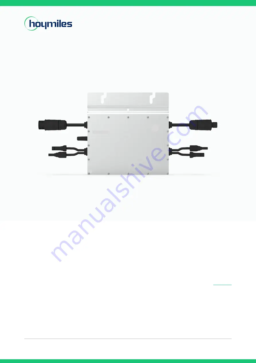
Single-phase Microinverter
USER MANUAL
HM-600
HM-600P
HM-700
HM-700P
HM-800
Region: Australia/New Zealand V202203
hoymiles.com
Page 1: ...Open Energy for All Single phase Microinverter USER MANUAL HM 600 HM 600P HM 700 HM 700P HM 800 Region Australia New Zealand V202203 hoymiles com...
Page 2: ...the production of a single PV module consequently improving the flexibility and reliability of the system About the Manual This manual contains important instructions for the HM 600 HM 600P HM 700 HM...
Page 3: ...nstallation Precautions 09 5 3 Required Space Distance 10 5 4 Grounding Considerations 10 5 5 Preparation 10 5 6 Installation Steps 11 6 Troubleshooting 13 6 1 Troubleshooting List 13 6 2 Status LED I...
Page 4: ...ower Electronics Inc All rights reserved 03 Single phase Microinverter User Manual Appendix 1 23 Installation Map 23 Appendix 2 24 WIRING DIAGRAM 230 VAC SINGLE PHASE 24 WIRING DIAGRAM 230 VAC 400 VAC...
Page 5: ...received training or has demonstrated competence may install and maintain this microinverter under the guidance of this document 1 3 Symbols Used The safety symbols in this user manual are shown below...
Page 6: ...OCPD Only one PV module can be connected to one input of the microinverter Do not connect batteries or other power supply sources The microinverter can be used only if all the technical characteristi...
Page 7: ...Directive for the European Union Read manual first Please read the installation manual first before installation operation and maintenance 2 3 Radio Interference Statement This microinverter has been...
Page 8: ...panels and offers high CEC weighted efficiency 96 50 peak efficiency 96 70 3 2 Highlights Maximum output power up to 600W 625W 700W 714W 800W Adapted to 60 cell 72 cell PV panels Peak efficiency 96 70...
Page 9: ...nto the public grid Zero Export Control In this mode the microinverter s generation is limited based on the current household loads and there is no extra power fed into the public grid Standby There a...
Page 10: ...o be purchased separately Please contact our sales representative for pricing information M8 screws need to be prepared by installer self 5 2 Installation Precautions Please install the microinverter...
Page 11: ...equipment is installed Installation must be carried out with the equipment disconnected from the grid power disconnect switch on and with the PV modules shaded or isolated Refer to the Technical Data...
Page 12: ...to form a continuous AC branch circuit Note The length of AC cable on microinverter is roughly 2 06 m if the distance between two microinverters is more than the AC cable please use an AC extension c...
Page 13: ...et ______ To sheet ______ To sheet ______ To sheet ______ Sheet_____of_____ Hoymiles Microinverter Installation Map Please Make N for North 1 A B C D 2 3 4 5 6 7 8 9 10 11 12 13 14 15 16 COLUMN ROW AP...
Page 14: ...special treatment is required 2 If the alarm occurs frequently and cannot be restored contact your dealer or Hoymiles Technical Service Center 127 Firmware error 1 Check if the firmware is correct and...
Page 15: ...r will automatically recover after grid frequency returns to normal 2 If the alarm occurs frequently check whether the grid frequency is within the acceptable range If it is not contact the local powe...
Page 16: ...occurs frequently and cannot be restored contact your dealer or Hoymiles Technical Service Center 302 Hardware error code 302 1 If the alarm occurs accidentally and the microinverter can still functio...
Page 17: ...e is corrupted Note All faults are reported to the DTU refer to the local DTU app or S Miles Cloud Hoymiles Monitoring Platform for more information 6 3 Insulation Resistance Detection There is a resi...
Page 18: ...ny anomalies 2 Always use the personal protective equipment provided by the employer when carrying out maintenance 3 During normal operation check that the environmental and logistical conditions are...
Page 19: ...DC connectors Use the AC disconnect tool to remove the AC connectors Unscrew the fixing screw on the top of the microinverter and remove the microinverter from the PV racking b How to replace the micr...
Page 20: ...void unforeseeable injury It is the customer s responsibility to examine the condition of the components transported Upon receiving the microinverter it is necessary to check the container for any ext...
Page 21: ...2 Power Quality Response Modes This inverter supports the following power quality response modes as per AS 4777 2 2015 Power derating for voltage variation Volt Watt mode The inverter output power va...
Page 22: ...n 9 1 DC Input Model HM 600 HM 600P HM 700 HM 700P HM 800 Commonly used module power W Up to 380 single panel Up to 440 single panel Up to 500 single panel Peak power MPPT voltage range V 29 48 33 48...
Page 23: ...ture range C 40 to 85 Dimensions W H D mm 250 170 28 Weight kg 3 00 Enclosure rating Outdoor NEMA 6 IP67 Cooling Natural convection no fans Pollution degree PD3 9 5 Features Model HM 600 HM 600P HM 70...
Page 24: ...dix 1 Installation Map To sheet ______ To sheet ______ To sheet ______ To sheet ______ Sheet_____of_____ Hoymiles Microinverter Installation Map Please Make N for North 1 A B C D 2 3 4 5 6 7 8 9 10 11...
Page 25: ...REEN G BRANCH END CAP L1 PHASE L1 ETHERNET CONNECTION TO BROADBAND ROUTER CONNECTION TO DTU POWER ADAPATER 5V DTU UP TO 49 MI 800s Appendix 2 WIRING DIAGRAM 230 VAC SINGLE PHASE BRANCH END CAP ETHERNE...
Page 26: ...AP L1 L2 L3 PHASE L1 PHASE L2 PHASE L3 ETHERNET CONNECTION TO BROADBAND ROUTER CONNECTION TO DTU POWER ADAPATER 5V DTU UP TO 49 MI 800s WIRING DIAGRAM 230 VAC 400 VAC THREE PHASE AC BRANCH CABLE BROWN...