4 210 256 / 01
17
Installation
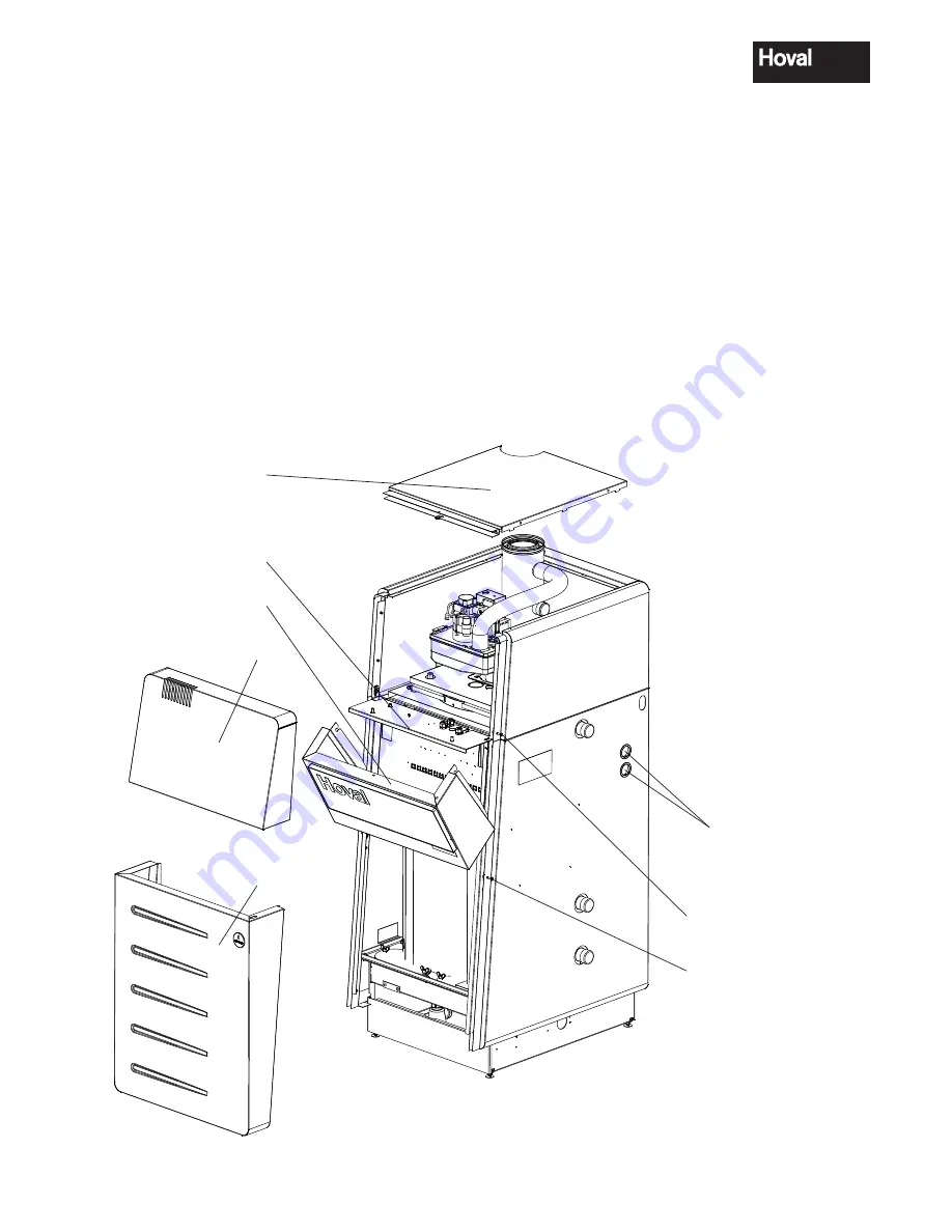
1. Remove front cover (1, fig. 10), after first releas-
ing the lateral locking bolt (1a) (turn approx. ¼
turn to the left and pull out as far as the stop). Lift
the front cover (1) straight upwards and remove
towards the front.
2. Lift and remove the lid (2).
3. Remove lower front cover (3), after first releasing
the lateral locking bolt (3a) (turn approx. ¼ turn
to the left and pull out as far as the stop). Slightly
raise the lower front cover (3) and remove to-
wards the front.
4. Remove the locking screw (4) on the right.
5. Lift the switch control box (5) and fold it out.
The electrical connection is to be made in accordance
with the diagram supplied.
4.4 Electrical connection
The electrical connection must be made by a qualified
electrical engineer.
For Austria and Germany:
An electrical circuit diagram is supplied with the boiler
controls. An all-pole main switch with a minimum contact
spacing of 3 mm must be fitted in the power supply line.
For Switzerland the following applies:
For the electrical connection, the electric circuit dia-
gram specific to the plant must be observed.
Fig. 10
Cable feed-in
2
5
1
3
1a
3a
4


